
Remote Control Toy Car Schematic
The remote control toy car schematic circuit diagram typically consists of several key components that work together to facilitate wireless control and operation. The main components include a transmitter, receiver, motor driver, and power supply.
The transmitter is responsible for sending control signals to the receiver located in the toy car. This is often achieved using a radio frequency (RF) module or an infrared (IR) transmitter, depending on the design specifications. The transmitter may include control switches or joysticks that allow the user to dictate the car's movements, such as forward, backward, left, and right.
The receiver, which is integrated into the toy car, decodes the signals received from the transmitter. It is typically paired with a microcontroller or a dedicated RF receiver module that interprets these signals and converts them into actionable commands for the motor driver.
The motor driver is a crucial component that interfaces between the receiver and the toy car's motors. It amplifies the control signals from the receiver to drive the motors effectively. Depending on the design, the motor driver may be a simple H-bridge circuit that allows for bidirectional control of the motors, enabling the car to move in both directions.
Power supply considerations are also essential in this circuit design. The toy car generally operates on a battery, which must provide sufficient voltage and current to power both the motors and the electronic components. Voltage regulators may be employed to ensure that the various components receive stable operating voltages.
In summary, the remote control toy car schematic circuit diagram integrates a transmitter, receiver, motor driver, and power supply, ensuring seamless operation while maintaining the original performance characteristics of the toy car.The following circuit shows about? Remote Control Toy Car Schematic Circuit Diagram. Features: does not impose on the performance of the original . 🔗 External reference
Related Circuits
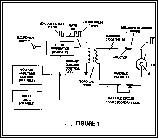
The fundamental concept involves a high-frequency, high-voltage, low-current signal that is rectified and subsequently utilized to charge a bank of high-value capacitors. These capacitors are then discharged in pulse mode for brief intervals, specifically in the nanosecond range, through...
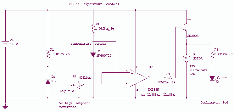
This circuit controls a load (in this case a DC brushless fan) based on a temperature compared with a setpoint. The transducer is a diode in the forward polarization regime. In fact, when forward biased, the forward voltage drop...
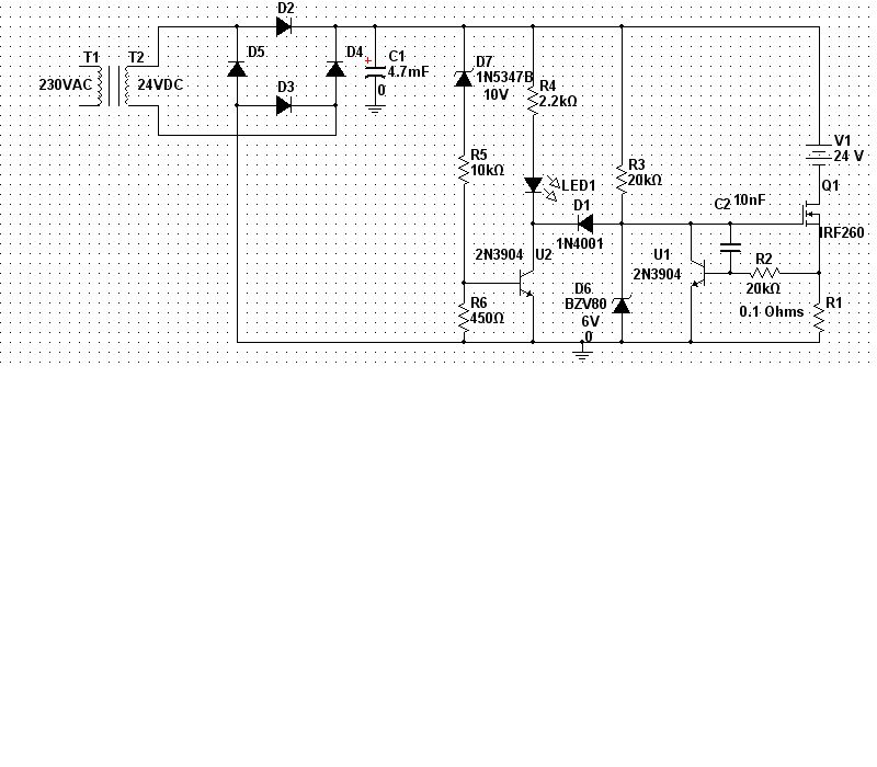
A 240/24Vac (rms) transformer is utilized, which after rectification and filtration provides approximately 30Vdc. It is crucial to select the transformer and diode ratings appropriately to meet the required specifications. In the current limiting stage, transistor U1, Q1, and...
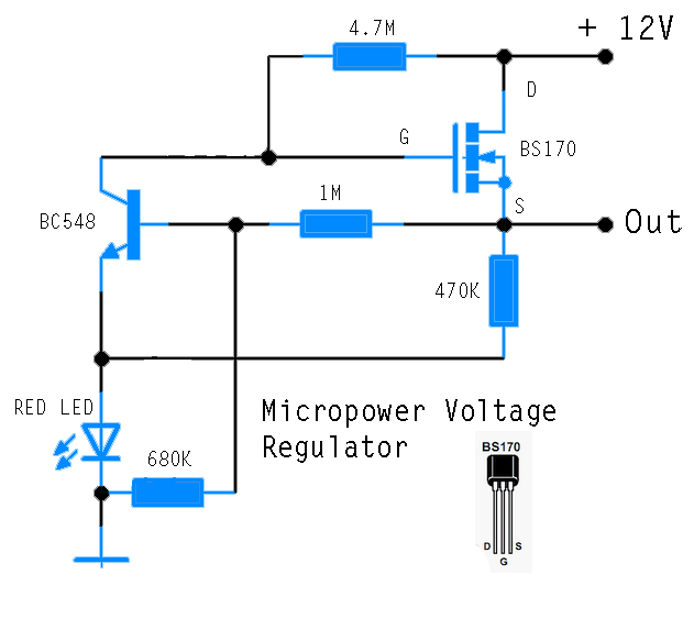
This circuit is designed to power an AVR microcontroller from a 12V lead-acid battery. The watchdog component consumes only 14 µA. While integrated circuits (ICs) from manufacturers like Linear Technology or Maxim can be utilized for this purpose, they...
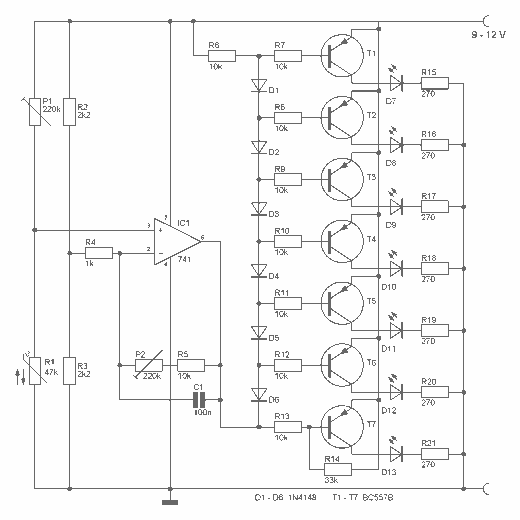
This digital thermometer indicates the temperature measured with an NTC using 7 LEDs. The circuit works using an opamp, the well-known 741, which amplifies the voltage difference between its plus and minus input. This amplification (sensitivity) can be set...
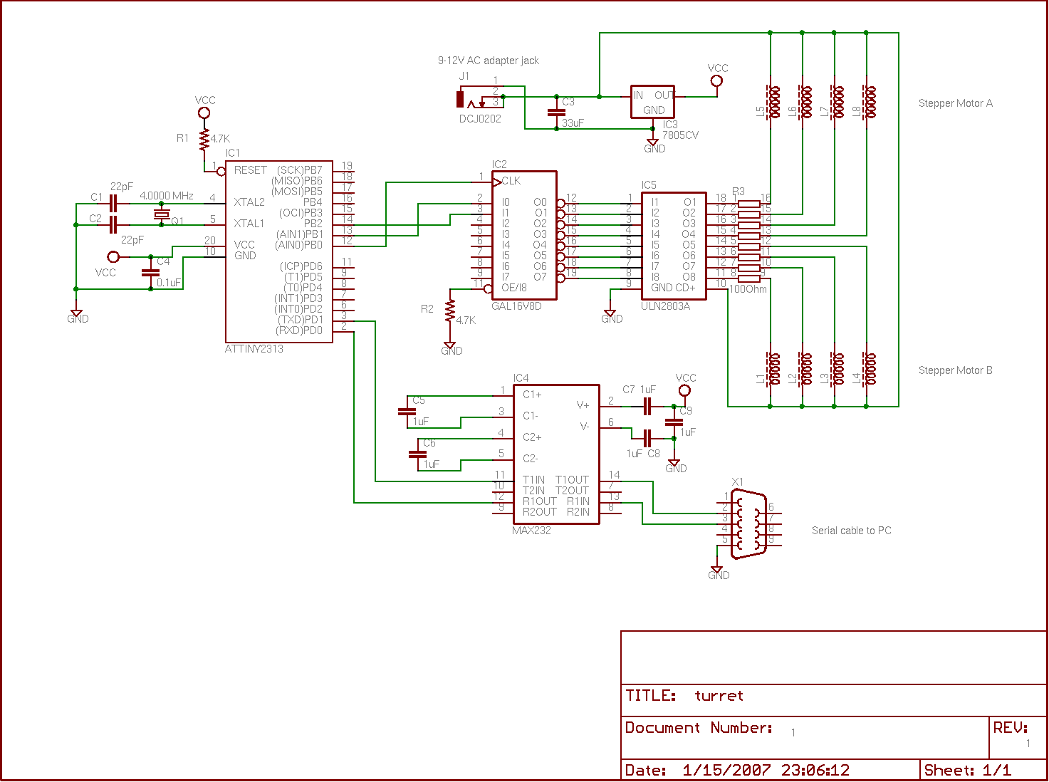
A tiny speedometer/trip computer was constructed using an Atmel ATTiny2313 microcontroller and an HD44780-compatible character LCD display, along with a reed switch and magnets. This device measured the speed of a soapbox derby cart by attaching a permanent magnet...