
12 Volt Supply Regulated
The described circuit employs a 13-volt zener diode (D2) to achieve voltage regulation. The zener diode functions by maintaining a stable output voltage across its terminals when reverse-biased, effectively clamping the voltage to approximately 13 volts. In this configuration, the voltage drop across the base-emitter (b-e) junction of the transistors is approximately 0.7 volts. This drop is typical for silicon transistors and is necessary for their operation in the active region.
The output voltage available from the circuit is approximately 12.3 volts, which is calculated by subtracting the 0.7 volts from the zener voltage. This output is suitable for powering various electronic loads, with the circuit capable of supplying a maximum current of 500 mA.
The amplified zener circuit design enhances the current drive capability of the zener diode, allowing it to handle higher loads without compromising voltage stability. The inclusion of transistors in the design serves to amplify the current, enabling the circuit to maintain the desired output voltage even under varying load conditions.
In practical applications, this circuit can be utilized in power supply systems where a stable voltage is crucial, such as in sensor applications, microcontroller power supplies, or other electronic devices requiring a regulated voltage source. Proper heat dissipation measures should be considered, as the transistors may generate heat during operation, especially when supplying currents near the maximum rating.This circuit above uses a 13 volt zener diode, D2 which provides the voltage regulation. Aprroximately 0.7 Volts are dropped across the transistors b-e junction, leaving a higher current 12.3 Volt output supply. This circuit can supply loads of up to 500 mA. This circuit is also known as an amplified zener circuit. 🔗 External reference
Related Circuits
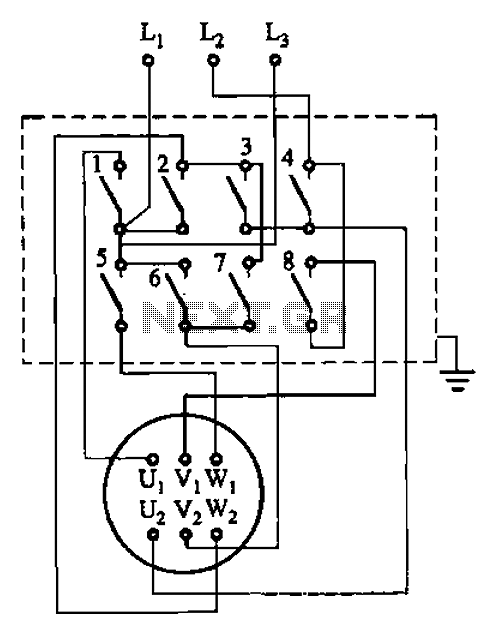
The circuit illustrated in Figure 3-36 includes the starter contact closure detailed in Table 3-1. In the figure, U1, V1, W1, and U2, V2, W2 represent the first three-phase stator windings of the motor terminals. The circuit depicted in Figure...
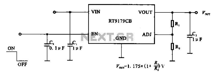
The RT9179CB is a power management chip utilized in power supply circuits. It serves as a linear regulator power management chip. This circuit is commonly employed in various products, such as computer motherboards, LCD monitors, and others. It is...
This is an add-on Over Voltage Circuit for the LM317 Regulator Circuit submitted by Matthew Hewson. It is a voltage regulator that allows a 6v portable supply to be derived from the 12v car battery. You can add a...
A 12V power supply is an essential and useful resource for laboratories, as it is employed by a wide range of electronic circuits and devices. A 12V power supply circuit can be constructed based on specific ampere requirements. A...
This circuit is designed to provide a 4 LED bar graph that indicates the voltage of a common 3.6-volt Lithium-Ion rechargeable cell phone battery. The reference voltage is supplied by a TL431 programmable voltage source, which is configured to...
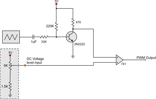
Circuits that generate PWM pulses typically translate a resistor value into a change in duty cycle. While this method is convenient, there are instances where a voltage-controlled PWM generator is required. Although microcontrollers can produce a variety of PWM...