
QX1 QX2 series magnetic starter Y- reduced-voltage starting circuit
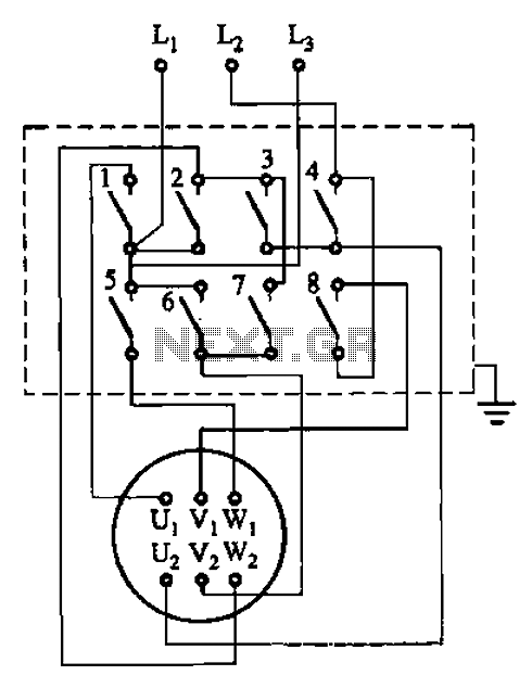
The circuit depicted in Figure 3-36 is a critical component of a three-phase motor control system. It demonstrates the configuration of the starter contact closure, which is essential for initiating the motor operation. The motor's stator windings are represented as U1, V1, W1 for the first set and U2, V2, W2 for the second set, indicating the dual winding arrangement typical in three-phase motors.
The starter contact closure, as referenced in Table 3-1, provides a systematic approach to energizing the motor. This closure is responsible for completing the circuit and allowing current to flow through the stator windings, which generates a rotating magnetic field necessary for motor operation. The interaction between the stator windings and the rotor creates torque, enabling the motor to perform work.
In practical applications, the design and layout of the circuit must ensure that the starter contacts are rated appropriately for the motor's operational current and voltage. It is also essential to incorporate protective elements such as fuses or circuit breakers to prevent damage to the motor and associated circuitry in the event of overloads or short circuits.
Furthermore, attention should be given to the phase sequence of the stator windings, as incorrect phasing can lead to reverse rotation of the motor. Proper labeling and connection of terminals U1, V1, W1, U2, V2, and W2 are crucial to maintain the correct operational parameters and ensure reliable performance of the motor system.
Overall, the configuration shown in Figure 3-36 is foundational for understanding the operation of three-phase motors and their control mechanisms, highlighting the importance of precise electrical connections and protective measures in motor applications. Circuit shown in Figure 3-36. Starter contact closure is shown in table 3-1. Figure, Ul, Vi, wl and U2, vz, W2 are the first three-phase stator windings of the motor terminal.
Related Circuits
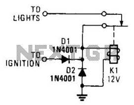
A relay and two diodes are all that is needed; the relay performs the job of a buzzer, so no annunciator is required. When the lights are left on while the ignition is off, the normally closed relay contacts...
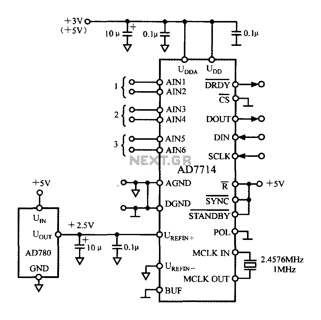
The typical application circuit for the AD7714 is illustrated in the accompanying figure. The UDD and UDDA terminals of the AD7714 can be connected to either a +3V or +5V power supply. The analog inputs are arranged as three...

NOR gates A and B create a low-frequency oscillator that activates when the CDS cell, in dark conditions, presents a logic zero to one input of NOR gate A. This low-frequency oscillator, operating at 10 Hz, enables a high-frequency...
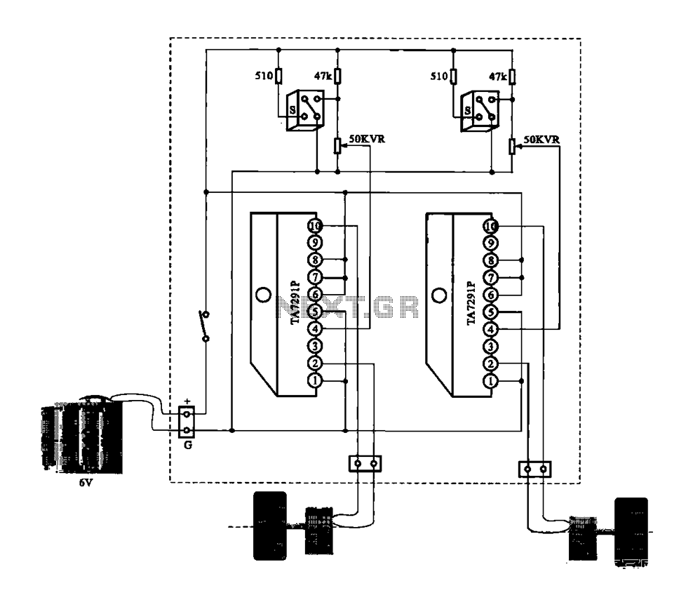
A dual motor drive circuit for automatic tracking consists of two motors that are part of a car structure, which operates based on the principles of a double motor drive system. The dual motor drive circuit is designed to facilitate...

FAN7710 Ballast Control circuit design for Compact Fluorescent Lamps electronic project. The FAN7710 is a specialized integrated circuit designed for the control of ballast systems in compact fluorescent lamps (CFLs). This circuit typically operates in a high-frequency range, facilitating efficient...
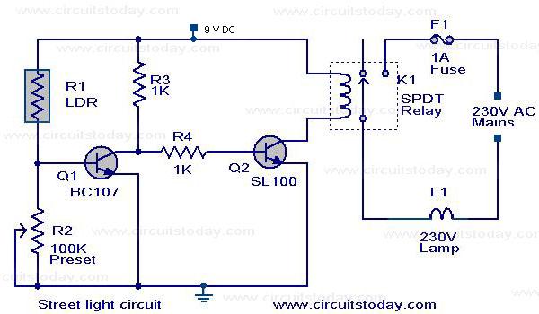
The circuit diagram of an Automatic Street Light Controller Circuit is explained in this post. The Automatic Street Light Controller Circuit is designed to automatically turn on street lights at dusk and turn them off at dawn. This functionality is...
Warning: include(partials/cookie-banner.php): Failed to open stream: Permission denied in /var/www/html/nextgr/view-circuit.php on line 713
Warning: include(): Failed opening 'partials/cookie-banner.php' for inclusion (include_path='.:/usr/share/php') in /var/www/html/nextgr/view-circuit.php on line 713