
120vac lamp chaser circuit

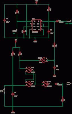
This circuit utilizes a 4017 decade counter to create a sequential lighting effect across multiple channels. The primary function of the 4017 is to count pulses and activate the corresponding output pins in a sequential manner. Each output pin can control a solid-state relay, which in turn controls the AC lamps. The relays are crucial for managing the higher voltage and current required by the AC lamps, while the 4017 counter operates at lower voltages suitable for logic circuits.
The circuit's design includes a timing mechanism, typically implemented using a 555 timer or similar oscillator circuit, generating a clock signal that drives the 4017. The clock frequency can be adjusted to change the speed of the LED chaser effect. The 360-ohm resistor plays a vital role in protecting the LED within the relay by limiting the current, ensuring that it operates within safe parameters.
In terms of expansion, the circuit can accommodate additional channels by integrating more relays and driver transistors. This scalability allows for a customizable number of outputs, depending on the user's requirements. The reset functionality of the 4017, connected to an output pin, enables the user to define the sequence length, allowing for flexible configurations of the lighting pattern.
For practical applications, this circuit can be utilized in various environments such as decorative lighting displays, stage lighting, or any scenario where sequential lighting effects are desired. The use of solid-state relays enhances the reliability and longevity of the circuit, as they do not have mechanical components that can wear out over time. Overall, this circuit design offers an efficient and effective solution for controlling multiple AC lamps in a sequenced manner.This circuit is design for same as the 10 channel LED sequencer with the addition of solid state relays to control the AC lamps. This circuit is control using relays. This is the figure of the circuit. The relay shown in the diagram is a Radio Shack 3 amp unit (part no. 275-310) that requires 1. 2 volts DC to activate. No current spec was given but I assume it needs just a few milliamps to light the internal LED. A 360 ohm resistor is shown which would limit the current to 17 mA using a 9 volt supply. I tested the circuit using a solid state relay (of unknown type) which required only 1. 5 mA at 3 volts but operates up to 30 volts DC and a much higher current. The chaser circuit can be expanded up to 10 channels with additional relays and driver transistors. The 4017 decade counter reset line (pin 15) is connected to the fifth count (pin 10) so that the lamps sequence from 1 to 4 and then repeat. For additional stages the reset pin would be connected to a higher count. 🔗 External reference
Related Circuits
This DC voltage doubler circuit generates a voltage that is double its supply voltage. It is beneficial when a higher voltage level is required from a single power source. The DC voltage doubler circuit typically employs a combination of capacitors...
A car alarm, in its simplest form, consists of one or more sensors connected to a siren. The most basic alarm features a switch on the driver's door, which is wired to trigger the siren when the door is...
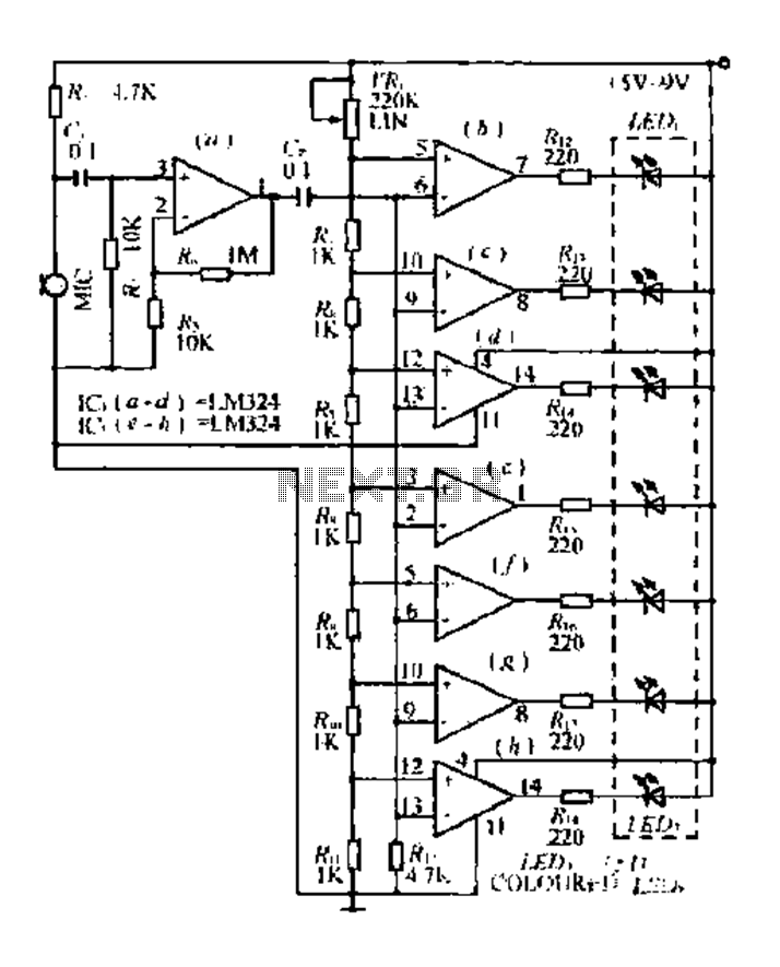
The condenser microphone pickup signal is processed by an integrated circuit (IC) where it is amplified and compared using a comparator circuit. The outputs from the comparators, designated as IC1, IC2, and IC3, provide voltage comparisons based on different...
A remote control light switch designed to fit into an existing light switch panel requires a 3.3V DC power supply for its electronics. However, the panel contains only two wires: one live wire and one wire that connects to...
This circuit includes a Relay Timer Circuit. One of the most commonly used circuits is that of the 555 Timer integrated circuit (IC). The circuit is designed to control a relay based on a timing interval. The Relay Timer Circuit...
This circuit is a simple -5V power supply using a 555 timer, designed for low-power analog applications involving FET operational amplifiers. The circuit converts +5V to -5V to create a dual power supply. It operates as a 555 astable...
Warning: include(partials/cookie-banner.php): Failed to open stream: Permission denied in /var/www/html/nextgr/view-circuit.php on line 713
Warning: include(): Failed opening 'partials/cookie-banner.php' for inclusion (include_path='.:/usr/share/php') in /var/www/html/nextgr/view-circuit.php on line 713