
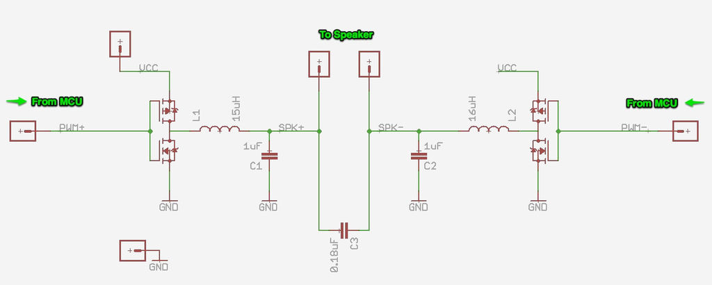
An external audio level display circuit
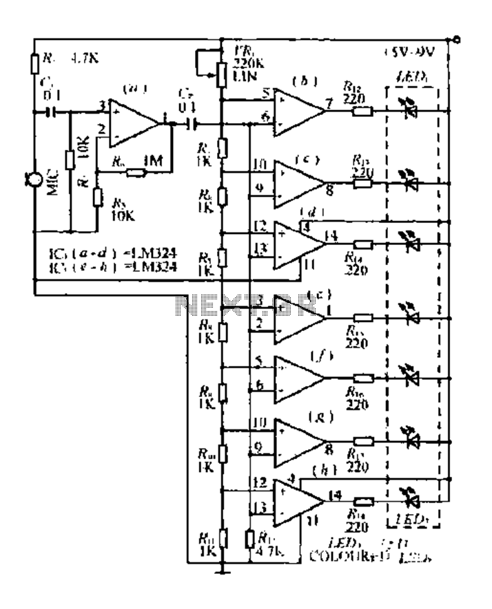
The circuit described utilizes a condenser microphone as the input device, which converts sound waves into an electrical signal. This signal is then amplified to ensure that it is suitable for further processing. The amplification stage is crucial, as it raises the signal to a level where it can be effectively compared against a predefined reference voltage.
The comparator circuit consists of multiple operational amplifiers configured to compare the amplified microphone signal against different threshold levels. Each comparator output corresponds to a specific audio level, enabling the detection of varying sound intensities. The outputs are connected to a series of light-emitting diodes (LEDs), which provide a visual representation of the detected audio levels. The arrangement of LEDs allows for a clear indication of the intensity of the input signal, with each LED illuminating at specific thresholds.
The resistor ladder formed by the variable resistor (VR) and fixed resistors (Ru and Rs) is an essential component of this design. This configuration allows for fine-tuning of the reference voltage used in the comparators, enabling adaptability to different audio environments or sensitivity requirements. By adjusting the variable resistor, the user can calibrate the circuit to respond appropriately to the desired sound levels, ensuring accurate detection and representation of audio signals.
Overall, this circuit design effectively combines audio signal processing, amplification, and visual output to create a versatile and user-friendly audio level detection system.Condenser microphone pickup signal broken by Iq. amplified and sent as a comparator HJ of lC.., - LC.., And lC: (e - b) each of the negative side, the positive terminal of the voltage comparison between wells. Output different detection levels, were light hair light: diode LEDl - LED7. The final show jumping corresponding audio level. VR. Ru and Rs a silk-linked to form a resistor ladder, unusual equipment is connected to the positive terminal of the comparator, the formation can delete the reference voltage.
Related Circuits
The fundamental principle of the theremin is the heterodyne oscillator. In the development of the Open Theremin, a stable and reliable oscillator was essential. Various schematics featuring different components were researched and constructed on small boards, which were then...
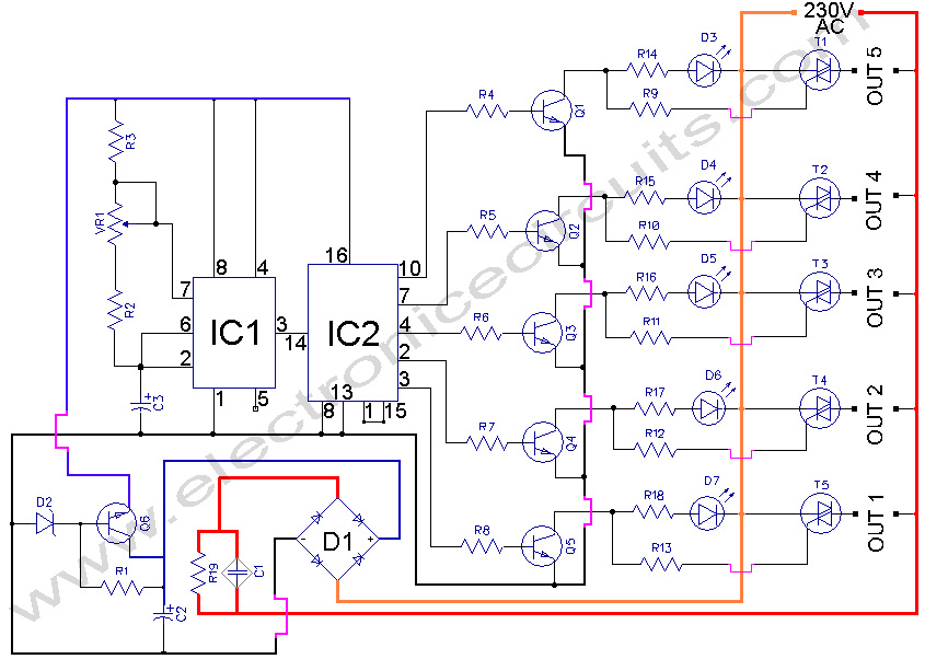
5 WAY AC FLASHER. These types of circuits are commonly used in various ceremonies such as the Wesak festival, Christmas, and weddings. This 5 WAY AC FLASHER circuit. The 5 Way AC Flasher circuit is designed to produce a sequential...

This circuit is designed as a countdown timer utilizing a countdown calculation. It employs the 555 integrated circuit (IC) as the primary control element. The 555 IC functions as a counter and a transistor switch to activate a relay...
Switching regulator subsystems intended for use as DC to DC converters. 3V to 40 Volt DC Converter circuit. The use of switching regulators is becoming more pronounced than that of linear regulators because the size reductions in new equipment...
If further information is desired regarding the circuit that powers the Sifteo Base audio, please continue reading. Otherwise, feel free to proceed to the next step. The Sifteo Base audio circuit is designed to provide audio output for interactive gaming...
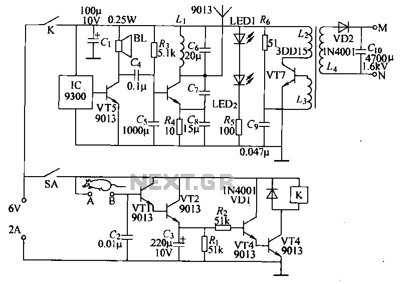
Power-saving electronic mousetrap. This example describes the minimal power consumption, which only occurs when a mouse enters the control zone during foraging activities. After a 30-second delay, the system enters a wait state, making it suitable for outdoor use....