
12v 30a regulated power supply
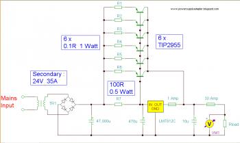
The circuit design incorporates several critical components to ensure efficient operation and safety. The input transformer or battery setup provides the necessary voltage headroom for the regulator. When using a transformer, the rectifier diodes must be rated for high peak currents, as they will experience significant stress during operation. The selected diodes should have a reverse voltage rating that exceeds the peak input voltage to prevent breakdown.
The 7812 voltage regulator serves as the primary regulation component, but its current capacity is limited. Therefore, external pass transistors (TIP2955) are utilized to handle the higher current demands of the load. These transistors are connected in parallel to distribute the load evenly, minimizing the risk of overheating and failure. Each transistor's dissipation is a fraction of the total load, but proper thermal management is crucial. A large heat sink is recommended to dissipate heat effectively, and the addition of a cooling fan or a water-cooling system may enhance reliability and performance.
The inclusion of a 1 amp fuse on the output of the regulator is a vital safety feature. It protects the circuit from overcurrent conditions that could lead to damage or catastrophic failure. This fuse will blow if the output current exceeds safe levels, thereby preventing excessive current from damaging the regulator or other components.
The 400 mΩ load serves a temporary purpose during testing and should not be part of the final design, as it can skew performance measurements and does not represent the operational characteristics of the intended load. Overall, the circuit is designed with robust components and safety features to ensure reliable operation under specified conditions.The input transformer is likely to be the most expensive part of the entire project. As an alternative, a couple of 12 Volt car batteries could be used. The input voltage to the regulator must be at least several volts higher than the output voltage (12V) so that the regulator can maintain its output. If a transformer is used, then the rectifier d iodes must be capable of passing a very high peak forward current, typically 100amps or more. The 7812 IC will only pass 1 amp or less of the output current, the remainder being supplied by the outboard pass transistors. As the circuit is designed to handle loads of up to 30 amps, then six TIP2955 are wired in parallel to meet this demand.
The dissipation in each power transistor is one sixth of the total load, but adequate heat sinking is still required. Maximum load current will generate maximum dissipation, so a very large heat sink is required. In considering a heat sink, it may be a good idea to look for either a fan or water cooled heat sink.
In the event that the power transistors should fail, then the regulator would have to supply full load current and would fail with catastrophic results. A 1 amp fuse in the regulators output prevents a safeguard. The 400mohm load is for test purposes only and should not be included in the final circuit. A simulated performance is shown below: 🔗 External reference
Related Circuits
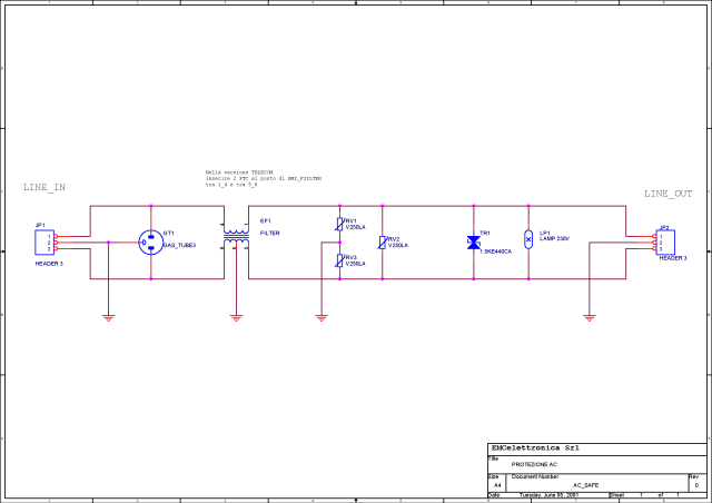
What is a circuit breaker? When is an AC power line filter or a phone line filter necessary? How can a noise filter be designed? Is it possible to create a homemade surge protector? The following circuit protection options...
This chapter presents detailed schematics for various power supplies compatible with commonly available Ar/Kr ion tubes in the surplus market. It includes examples of commercial designs such as the Omnichrome 150R and 532 head, Lexel 88 and head, alongside...
Logic power control of an analog regulator can be useful in applications where a digital circuit or controller needs to manage a power source, such as in EEPROM. In electronic systems, managing power effectively is crucial for the performance and...
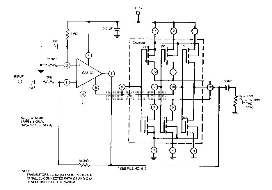
This circuit effectively enhances the current-sourcing and current-sinking capabilities of the CA3130 BiMOS operational amplifier. This configuration increases the current-handling capacity of the CA3130 output stage by approximately 2.5 times. The circuit described is designed to augment the output performance...
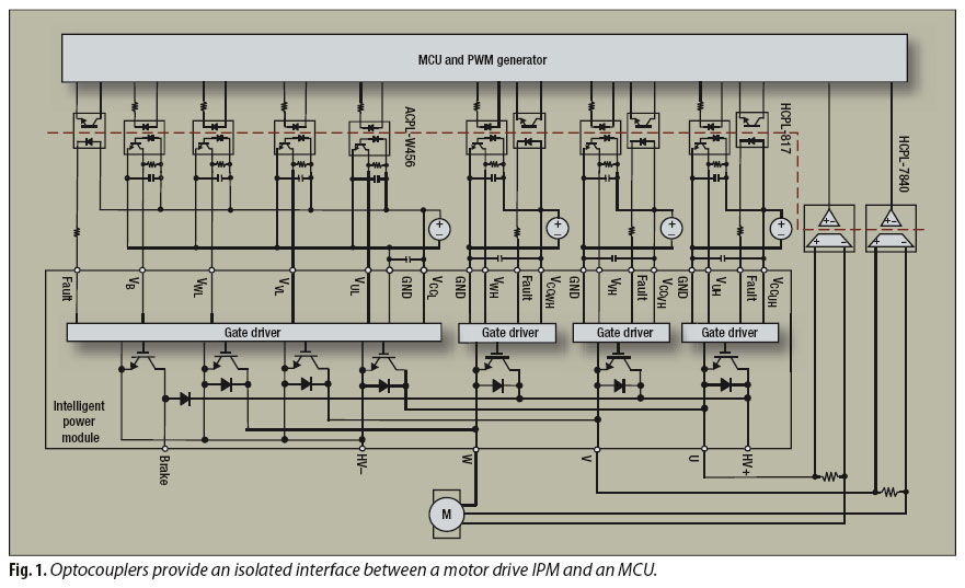
An interface circuit utilizing optocouplers provides galvanic isolation and common-mode noise rejection between low-voltage microcontroller units and high-voltage integrated power modules in motor-drive applications. Optocouplers ensure high-voltage isolation between a low-voltage device, such as a microcontroller or a pulse-width...
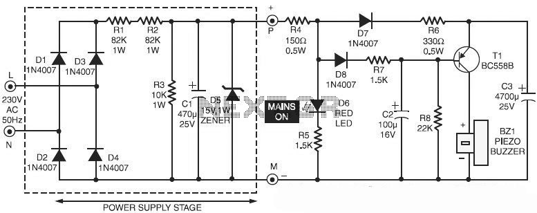
This is a specialized circuit design for a power supply failure alarm. Most power supply failure alarm or indicator circuits require an independent power supply. However, the alarm circuit presented here... The power supply failure alarm circuit is designed to...