
optocouplers safely isolate integrated power modules
The described interface circuit is crucial for ensuring safe and reliable operation in motor-drive applications where both low and high voltage components are present. The use of optocouplers not only fulfills safety requirements but also enhances system performance by minimizing noise and interference. In practical applications, the selection of optocouplers must be based on their voltage ratings, isolation characteristics, and compliance with relevant safety standards, ensuring that the circuit can operate effectively under various conditions.
The integration of isolated amplifiers for feedback from the motor phases is essential for maintaining control over the motor's performance. These amplifiers provide critical information about the current running through the motor, allowing the microcontroller to make real-time adjustments to optimize performance and protect against overcurrent conditions.
Furthermore, the design of the power supply for the gate drivers is a significant consideration. The requirement for floating grounds in high-side driver circuits is a common challenge in power electronics. The implementation of bootstrapping techniques can simplify the power supply design while ensuring that each gate driver functions correctly, even as the high-side IGBTs switch states.
In summary, the interface circuit utilizing optocouplers and isolated feedback mechanisms is a sophisticated solution for the challenges faced in high-voltage motor-drive applications. The careful selection of components and adherence to safety standards are paramount in creating a reliable and efficient system.An interface circuit based on optocouplers provides galvanic isolation and common-mode noise rejection between low-voltage microcontroller units and high-voltage integrated power modules in motor-drive applications. Optocouplers provide high-voltage isolation between a low-voltage device like a microcontroller or a pulse-width modulation (PWM) gen
erator and a high-voltage device like an intelligent or integrated power module (IPM). The optocoupler is a key interface device because every high-voltage circuit must be compliant with equipment safety standards, such as IEC 60950 for IT equipment and IEC 60335 for household appliances. In testing for these standards, a high voltage is usually applied between low-voltage and high-voltage ports of the equipment.
In these systems, the optocoupler isolates the low- to high-voltage interface to meet safety and protection standards. Some common semiconductor component electrical safety standards applicable to optocouplers are IEC 60747-5-2 and UL 1577.
A designer can select the appropriate optocouplers based on the relevant equipment safety standards. The table lists the characteristics of some optocouplers intended for high-voltage isolation. The key optocoupler parameters related to equipment safety ratings are working voltage, polluting degree, installation class and insulation level. Various safety standards for industrial, home, office and IT equipment require a reinforced insulation level for electrical equipment powered by the ac line.
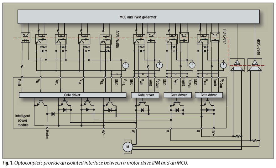
Some parameters specified by equipment safety standards include external clearance, creepage, distance through insulation (DTI) or internal clearance, and comparative tracking index (CTI). Fig. 1 shows a diagram of a motor-drive circuit between a microcontroller unit (MCU) and an IPM. Seven units of digital optocoupler ACPL-W456 isolate the IPM`s seven gate driver inputs, one for the brake and six for the IGBTs.
Using voltage sampling from two shunt resistors, two HCPL-7840 isolated amplifiers provide linear feedback from two motor phases to the MCU. Four HCPL-817 general-purpose phototransistor-type optocouplers isolate the IPM`s fault feedback signals.
All these optocouplers are compliant with reinforced safety-protection levels, because they secure a galvanic isolation boundary between low- and high-voltage circuits. A three-phase IPM employs six gate drivers each for six high- and low-side IGBTs. Each gate driver needs a 10-V to 30-V power supply. The emitters of the low-side IGBT connect to the dc bus HV- as common reference ground, which allows all low-side gate drivers to share the same power supply (VCC_L - GND1).
Also integrated are overtemperature and overcurrent protection functions that feedback a fault signal to the host microcontroller. The emitter of the high-side IGBT and the collector of the low-side IGBT connect to form one leg of a three-phase switch.
By alternately turning high-side and low-side IGBTs on and off, the HV dc bus voltage switches the output to the respective phase of U, V or W load. The three-phase vectors are 120 degrees apart. With ground connecting to the collector of the low-side IGBTs, the ground of each high-side gate-driver circuit swings between HV- and HV+.
Thus, the ground of each power supply for the high-side IGBT gate-driver circuit must float and be separated from each other. A more robust solution is to have three isolated power supplies to each high-side gate-driver circuit.
Bootstrapping the power supply with individual floating grounds is a cost-effective alternative. You can derive a bootstrapping power supply from either dc bus voltage or low-side power supply VCC_L. Conventional IPM input logic and gate-driving circuits are integrated on a monolithic IC, and their power supply ranges from 15 V to 20 V.
This conventional IPM has an inverted logic. When the input voltage is high, the IGBT turns off; when the input voltage is low, the 🔗 External reference
Related Circuits
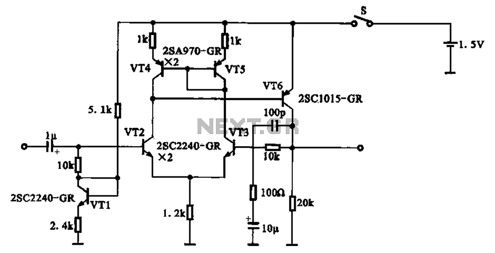
A 1.5V-powered microphone signal amplifying circuit is designed with a power supply for the microphone signal amplification. The circuit primarily consists of a differential amplifier formed by transistors VT2 and VT3. Additionally, VT6 functions as a common emitter voltage...
The circuit is based on a single operational amplifier integrated circuit designed to produce a modular preamplifier that operates in Class A configuration. The modular preamplifier circuit utilizes a single operational amplifier (op-amp) integrated circuit, which serves as the primary...
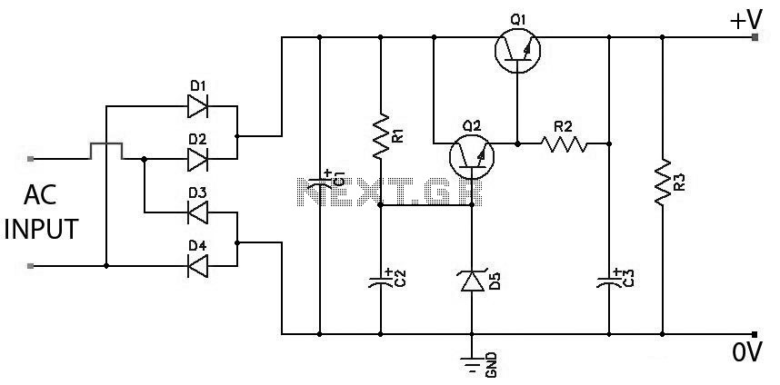
Low Ripple Regulated Power Supply Circuit Diagram. This circuit can be employed in applications requiring high current with minimal ripple voltage, such as in high-powered class AB amplifiers where high-quality audio reproduction is essential. The low ripple regulated power...
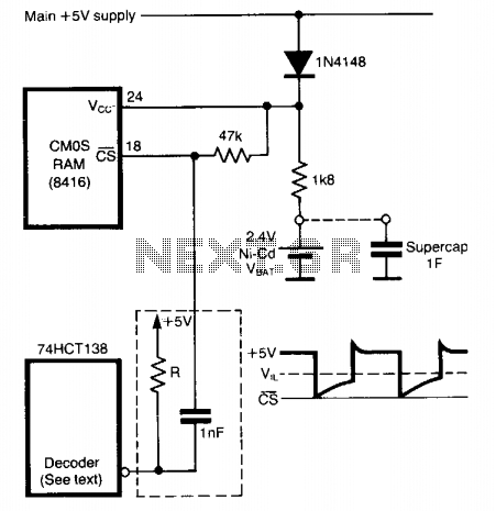
To prevent data loss when a CMOS RAM transitions from normal operation (Vcc = 5 volts) to standby mode (Vcc = VBAT), it is crucial to maintain the CS pin close to the Vcc rail at all times. This...
A DC-DC power supply schematic is required that outputs a voltage between 12.7V and 14.5VDC, with an input voltage range from 12VDC upwards. The design of a DC-DC power supply capable of outputting a regulated voltage between 12.7V and 14.5VDC...
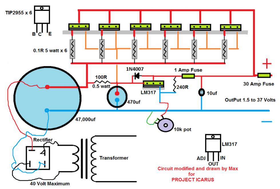
This circuit was designed and manufactured in the 1980s. Since then, it has operated without issues. There are no specific construction challenges, aside from the usual considerations: attention to the power supply requirements, selection of an appropriate heatsink, and...