
12V Battery Level Indicator Circuit
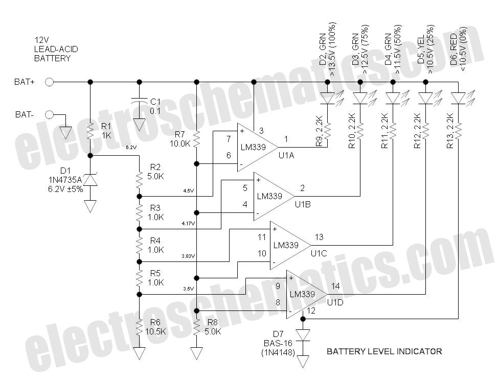
The battery level indicator circuit utilizes a series of five light-emitting diodes (LEDs) to provide a visual representation of the battery voltage level. The circuit is designed to activate each LED at specific voltage thresholds, allowing users to easily assess the battery's charge status.
The first LED, colored red, serves as a power connection indicator, illuminating when the battery is connected but not yet charged, indicating 0% charge. The second LED, colored yellow, activates when the battery voltage exceeds 10.5V, representing a charge level of approximately 25%.
As the voltage continues to rise, additional LEDs are activated at predetermined voltage levels. For instance, the third LED could illuminate at 12.0V, indicating a charge level of around 50%. The fourth LED might activate at 12.5V, representing 75% charge, while the fifth LED, typically colored green, would light up when the voltage reaches 13.0V or higher, indicating a fully charged battery.
The circuit can be implemented using a voltage divider to scale down the battery voltage to a suitable level for comparison with reference voltages. Comparators or microcontroller analog inputs can be employed to detect when the voltage crosses these thresholds, triggering the corresponding LED to light up.
This battery level indicator is particularly useful in various applications, including portable devices, electric vehicles, and renewable energy systems, where monitoring battery status is crucial for optimal performance and longevity.This battery level indicator offers (5) LEDs that light up progressively as the voltage increases: Red: Power Connected (0%) Yellow: Greater than 10.5V (25.. 🔗 External reference
Related Circuits
The IC1 is a 555 timer IC configured for astable operation, generating clock pulses that are fed to IC2 through a 10K resistor. IC2 is a 10-stage counter, with output 6 (pin 5) connected to RESET (pin 15), resulting...
The circuit utilizes a quad voltage comparator (LM339) as a basic bar graph meter to display the charge status of a 12-volt lead-acid battery. A 5-volt reference voltage is applied to each of the positive (+) inputs of the...
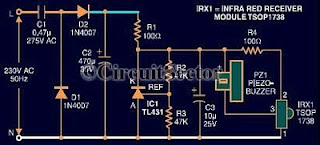
An infrared remote control tester circuit that can be constructed inexpensively. This IR tester is built around an infrared receiver module TSOP1738. The remote control's state can be observed through the sound of a buzzer. The circuit is highly...
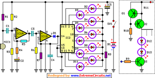
The basic circuit illuminates up to ten LEDs in sequence, following the rhythm of music or speech picked up by a small microphone. The expanded version can drive up to ten strips, each formed by up to five LEDs,...
LEDs are rated for a continuous current of only 30 mA, while this circuit operates them at approximately 50 mA. Although this is acceptable for low duty cycles with short pulses, the intended design has a high duty cycle....
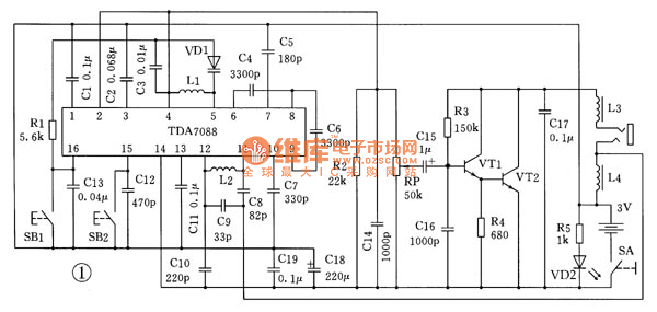
This is the schematic diagram for an automatic search FM radio. The primary component is the TDA7088 integrated circuit, which encompasses the FM radio receiver, antenna, oscillator, mixer, automatic frequency control (AFC) circuit, intermediate frequency amplifier (with an IF...