
The application circuit of TDA7088 FM integrated circuit
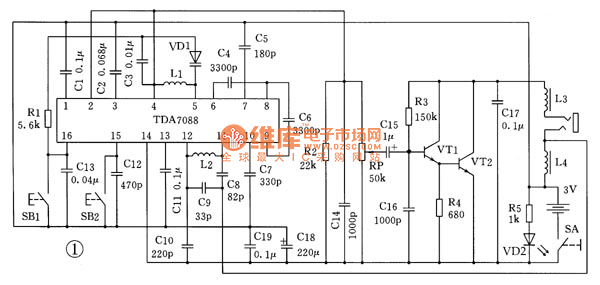
The FM radio schematic utilizes the TDA7088 integrated circuit as its central element, which integrates multiple functionalities required for FM signal processing. The circuit begins with an antenna that captures radio frequency signals, which are then fed into the FM radio receiver section of the TDA7088. This receiver demodulates the incoming signals, allowing for the extraction of the audio content.
The oscillator within the TDA7088 generates a local frequency that mixes with the incoming signal in the mixer stage. This mixing process produces intermediate frequencies, which are then amplified by the intermediate frequency amplifier. The specified IF frequency of 70 kHz is a critical parameter, as it determines the performance characteristics of the entire circuit.
The IF limiter and filter stages ensure that only the desired frequency components are passed through while suppressing unwanted noise. The frequency discriminator converts the frequency variations of the FM signal into amplitude variations, which can then be processed further. The low-frequency squelch circuit is employed to mute the audio output during periods of weak signal reception, thereby enhancing the listening experience by eliminating background noise.
The search tuning circuit is designed to automatically scan through available FM stations, locking onto the strongest signal detected. This feature is complemented by the signal detection circuit, which evaluates the strength and quality of the received signals to optimize tuning performance.
The frequency-locked loop (FLL) maintains the tuning stability of the circuit, ensuring that the selected station remains locked even in the presence of minor frequency shifts due to signal drift or interference.
In terms of component selection, the circuit can utilize a varactor diode as a replacement for traditional variable capacitors. The varactor diode's capacitance is voltage-dependent, allowing for electronic tuning of the circuit without the need for mechanical adjustments. This characteristic is particularly beneficial in compact designs where space is at a premium.
Overall, the schematic diagram of the automatic search FM radio represents a sophisticated integration of various electronic components, all working in concert to deliver a reliable and user-friendly radio experience.This is the automatically search schematic diagram of FM radio. Its core component is a TDA7088 integrated circuit which includes FM radio receiver, antenna, oscillator, mixer, AFC ( frequency automatic control) circuit, intermediate frequency amplifier ( IF frequency is 70kHz), IF limiter, IF filter, frequency discriminator, low frequency squ elch circuit and audio output; it also specifically sets search tuning circuit, signal detection circuit and frequency locked loop. It can use a varactor diode to replace the variable capacitor is, which is a special kind of diodes. The PN junction capacitance is changed with the bias voltage ( reverse voltage) on PN junction. 🔗 External reference
Related Circuits
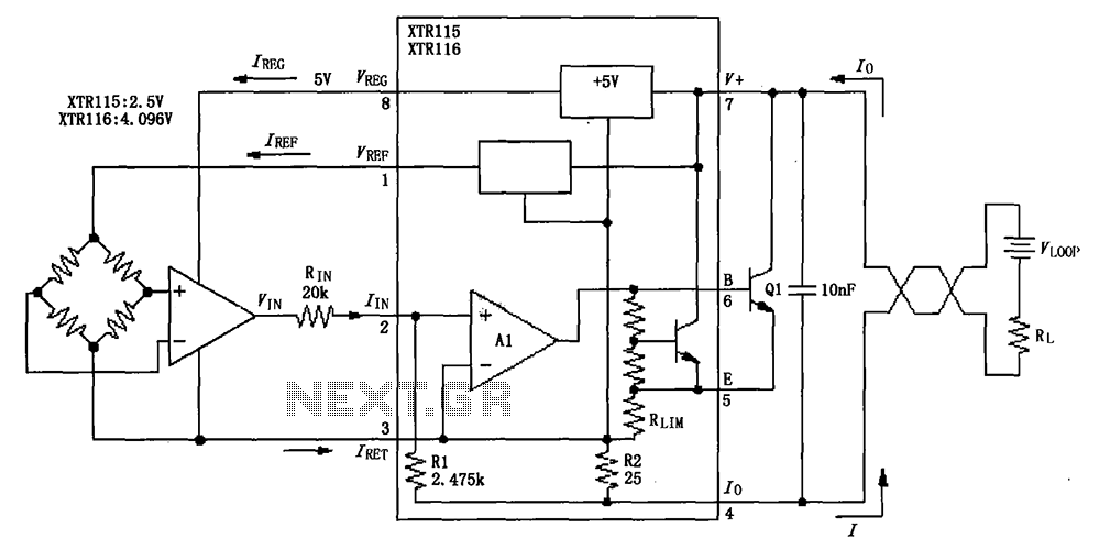
The output reference voltage VREF from the O pin is not utilized within the internal circuit; instead, it is provided to the external circuit. Similarly, the output voltage VREG is also supplied to the external circuit. All current return...
The initial intention was to name the product "Chimera," but due to an existing synth company with that name, it was decided to use "Cerberus" to avoid confusion. The term "Tricephalic Filter" was deemed less appealing. Similar to its...
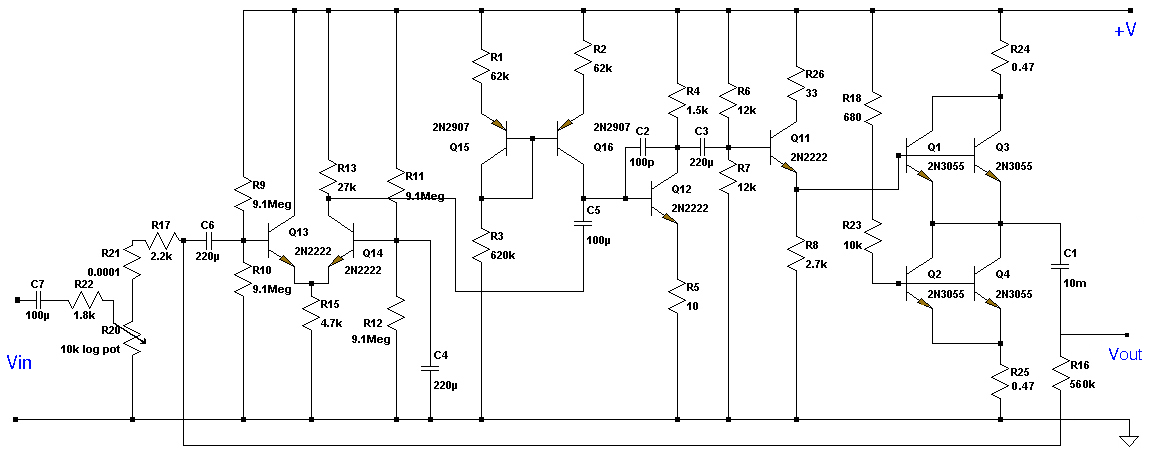
This Class A preamplifier features a symmetrical design. The input differential stages utilize dual transistors, T1 and T2. Polarization correction is crucial due to amplification discrepancies and is managed by transistor T12. Potentiometer P2 adjusts the output voltage to...
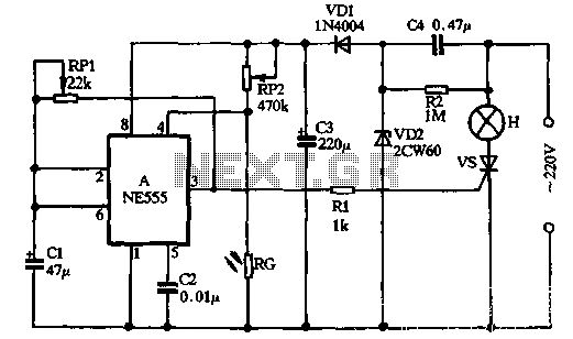
VDI, VD2, C3, and C4 form a simple half-wave rectifier capacitor step-down regulator circuit. This circuit can output approximately 12V DC voltage after power is applied across C3, which is utilized for the time base circuit. Additionally, the time...
This circuit is a simple series tone control circuit utilizing the OP-Amp LM301A. The JFET 2N3684 provides high input impedance and low noise characteristics for the feedback buffer in the op-amp-based tone control. The tone control circuit described employs an...
Assortment of siren circuits. This month, three different types of siren circuits are being created based on the 555 timer. The first circuit simulates the siren of a British police car. It utilizes two 555 timers. The design of the...