
12v battery level indicator circuit led
Additionally, a simple battery level indicator can be implemented using the MN13811G from Panasonic, which serves as a CMOS voltage detector IC suitable for various voltage monitoring applications. In this circuit, LED D1 will flash whenever the battery voltage falls below 2.4 volts. Another configuration is a 3 LED battery level indicator for monitoring a 12V automobile battery, where three states of the battery voltage (below 11.5V, between 11.5V and 13.5V, and above 13.5V) are indicated by the glowing of the respective LEDs. Furthermore, a flashing battery monitor circuit can be designed for 6 to 12V batteries based on transistors, with the voltage level at which the LED begins to flash being adjustable via a potentiometer.
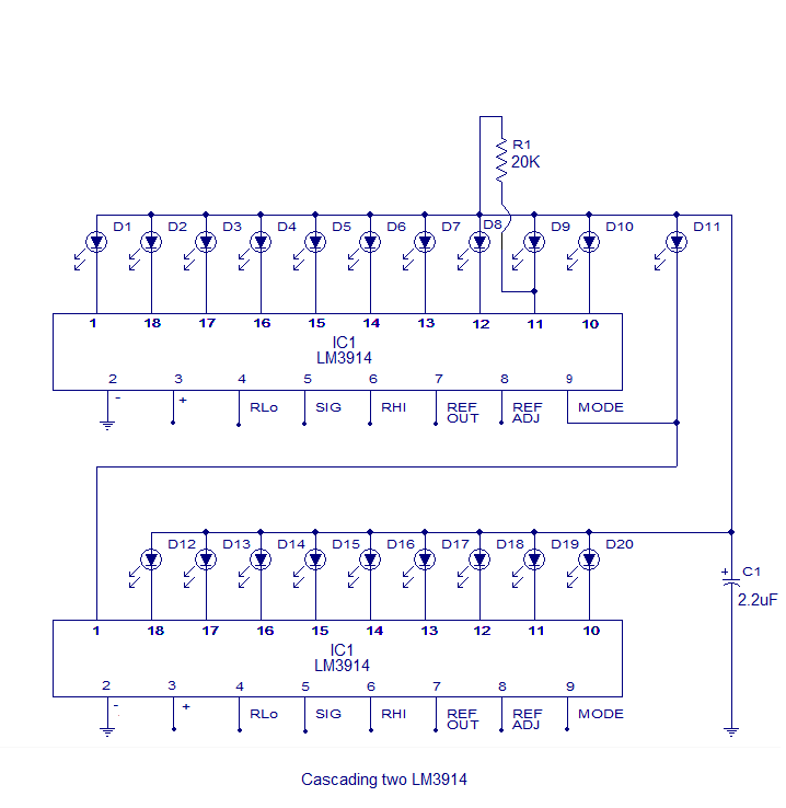
These circuits provide versatile solutions for battery monitoring applications, enabling visual feedback on battery status through LED indicators.The heart of this circuit is the LM3914 from national semiconductors. The LM3914 can sense voltage levels and can drive a display of 10 LEDs in dot mode or bar mode. The bar mode and dot mode can be externally set and more than one ICs can be cascaded together to gat an extended display. The IC can operate from a wide supply voltage (3V to 25V DC) . The brightness of the LEDs can be programmed using an external resistor. The LED outputs of LM3914 are TTL and CMOS compatible. In the circuit diagram LEDs D1 toD10 displays the level of the battery in either dot or bargraph mode. Resistor R4 connected between pins 6, 7 and ground controls the brightness of the LEDs. Resistors R1 and POT R2 forms a voltage divider network and the POT R2 can be used for calibration. The circuit shown here is designed in order to monitor between 10. 5V to 15V DC. The calibration of the circuit can be done as follows. After setting up the circuit connect a 12V DC source to the input. Now adjust the 10K POT to get the LED10 glow (in dot mode) or LEDs up to 10 glow (in bar mode). Now decrease the voltage in steps and at 10. 5 volts only LED1 will glow. Switch S1 can be used to select between dot mode and bar graph mode. When S1 is closed, pin9 of the IC gets connected to the positive supply and bar graph mode gets enabled.
When switch S1 is open pin9 of the IC gets disconnected to the positive supply and the display goes to the dot mode. With little modification the circuit can be used to monitor other voltage ranges. For this just remove the resistor R3 and connect the upper level voltage to the input. Now adjust the POT R2 until LED 10 glows (in dot mode). Remove the upper voltage level and connect the lower level to the input. Now connect a high value POT (say 500K) in the place of R3 and adjust it until LED1 alone glows. Now remove the POT, measure the current resistance across it and connect a resistor of the same value in the place of R3.
The level monitor is ready. Two or more LM3914 ICs can be cascaded together to get anextendeddisplay. The schematic of two LM3914 ICs cacaded together to get a 20 LED voltage level indicator is shown below. 1. Simple battery level indicator : This circuit can be used for monitoring the level of 3V batteries. The circuit is based on MN13811G from Panasonic. MN13811G is a CMOS voltage detector IC that can be used a variety of voltage monitoring applications.
In the circuit LED D1 will flash when ever the battery voltage drops below 2. 4 volts. 2. 3 LED battery level indicator : A 3 LED battery level indicator that can be used for monitoring the voltage level of 12V automobile battery is shown here. Three states of the battery ie; below 11. 5V, between 11. 5 and 13. 5 and above 13. 5 are shown by the glowing of LEDs. 3. Flashing battery monitor : This circuit can be used for monitoring the voltage level of 6 to 12V batteries.
The circuit is based on transistors and the voltage level at which the LED starts flashing can be adjusted by using a potentiometer. 🔗 External reference
Related Circuits
This series-feedback configuration of compounds provides a high input impedance and stable, wide-band gain video amplifier suitable for general-purpose applications. It features low capacitance and high impedance. The described video amplifier circuit utilizes a series-feedback topology to achieve high input...
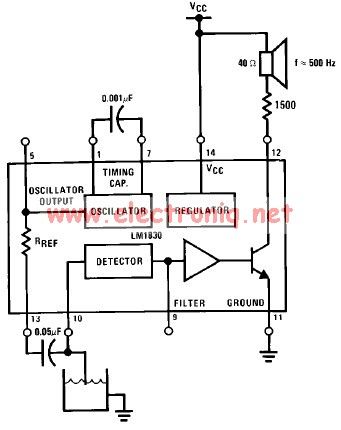
The LM1830 low-level detector can utilize an audio indication (speaker) or a visual indicator (LED - light-emitting diode) that activates when the level is too low. This low-level detector circuit generates a 500 Hz audio signal when the level...

The drivers can operate fourteen LEDs, but only twelve are currently used. This allows for the addition of twelve LEDs to the existing setup without requiring additional drivers. The device is powered by a 120VAC plug, supplying power to...
A sine wave oscillator can be implemented using a Wien-Bridge oscillator, similar to the previous sine wave oscillator circuit; however, another method is now presented. The Wien-Bridge oscillator is a type of electronic oscillator that generates sine waves. It is...
The circuit described utilizes a quad voltage comparator (LM339) to function as a simple bar graph meter that indicates the charge status of a 12-volt lead-acid battery. A 5-volt reference voltage is employed for this purpose. The circuit leverages the...

Cable and xDSL modems are increasingly popular, leading to a need for designs that interface with existing telephones at subscriber locations. The subscriber line interface circuit (SLIC) within the modem must ring the phone and provide loop current during...