
12V LDO Solar Charge Controller
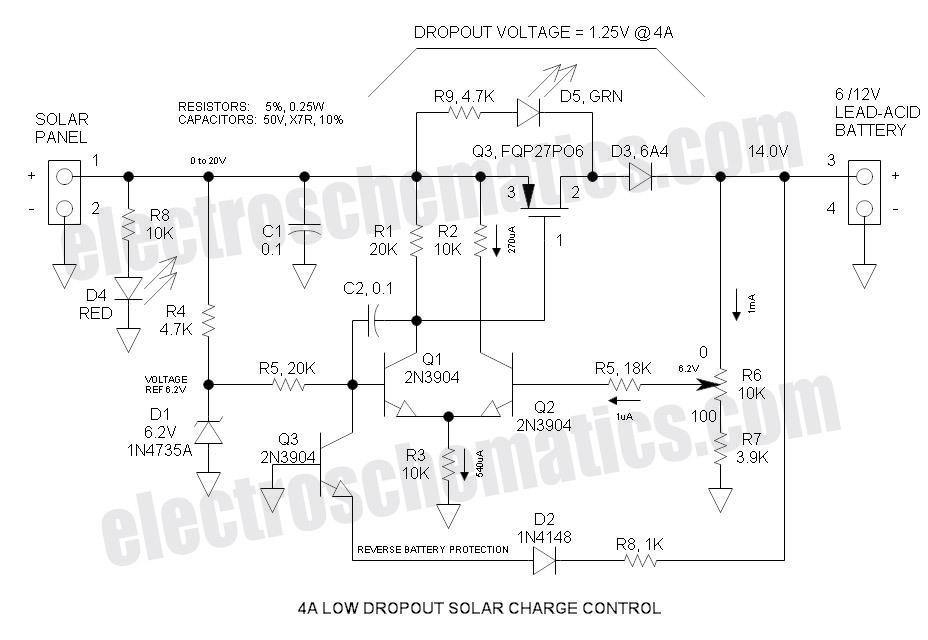
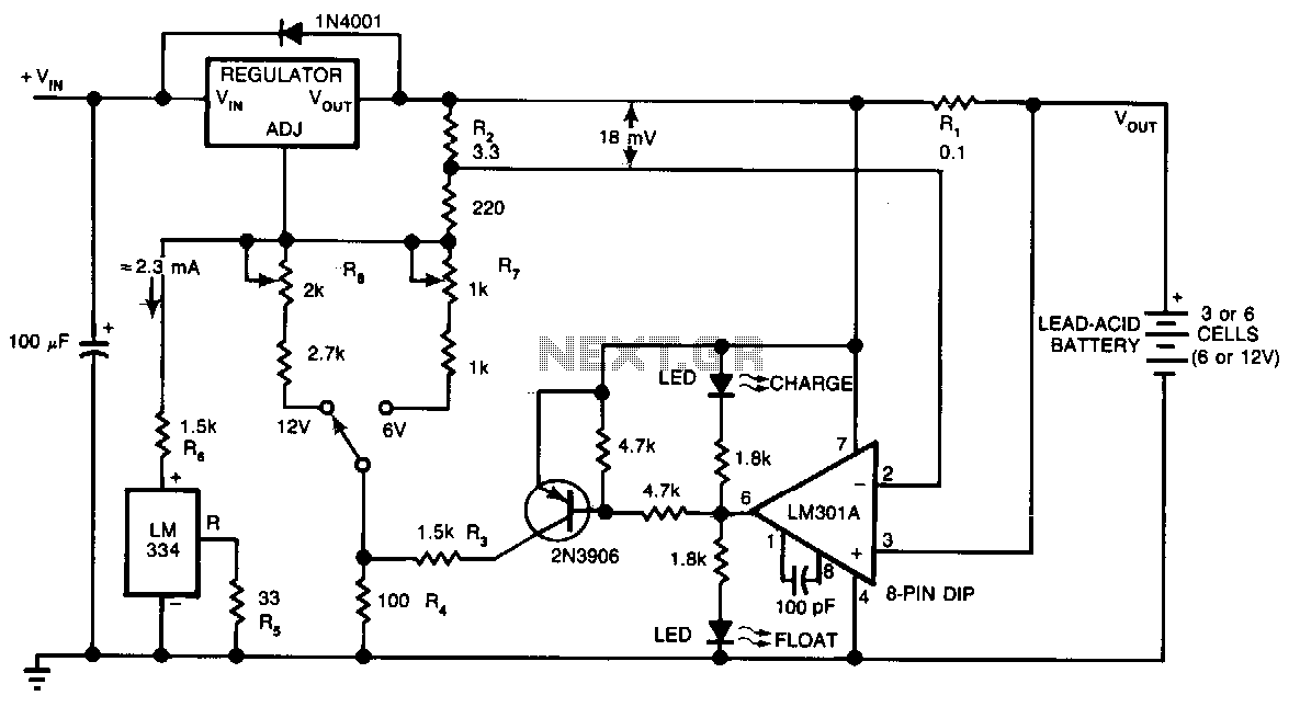
To set the voltage, the battery must be disconnected, and a 1K dummy load resistor should be connected to the output to shunt potential MOSFET leakage current and the current for the green LED indicator. R4 and D1 create a 6V shunt Zener voltage reference. Q1 and Q2 form a classic differential amplifier that amplifies the difference between the reference voltage and the feedback voltage from the potentiometer arm of R6. The output from Q2 drives the gate of P-channel MOSFET Q3. The differential voltage gain is estimated to be between 100 and 200. For optimal performance, Q1 and Q2 are selected for matched hFE. As the feedback voltage at R6 increases, Q2 becomes more conductive, diverting some emitter current away from Q1. The collector current of Q1 follows the emitter current, resulting in a reduced voltage drop across R1, which decreases the gate-source voltage (Vgs) of Q3, turning it off. Capacitor C2 provides frequency compensation, preventing the amplifier from oscillating.
Q3 remains inactive unless the battery is connected in reverse; in this case, Q3 activates, reducing the reference voltage to zero, thus protecting the circuit from damaging reverse battery current. This design functions as a linear series regulator that dissipates significant power when the pass transistor is both conducting current and dropping voltage. During maximum charge rates with low voltage drops, the heatsink remains warm. Conversely, when the battery is fully charged and the charge current is low, the heatsink is cool. However, as the battery approaches maximum voltage, the heatsink temperature increases significantly. For instance, at a current of 4A, Q3 experiences a voltage drop of 3.3V (assuming the solar panel voltage is 18V), with a remaining drop of 0.7V across D3, resulting in a power dissipation of 13.2W. Given a heatsink rating of 3.9 °C/W, the temperature rise of the heatsink would be approximately 51.5 °C. Adding the ambient temperature of 25 °C yields a total heatsink temperature of 76.5 °C. While this temperature may feel very hot to touch, it remains within safe limits for the transistor, which is rated for a junction temperature of 175 °C. A 6V version of this controller is under consideration, which could be adjusted down to 7V for charging 6V batteries; however, performance would be marginal and at reduced current levels.This Low Dropout Voltage (LDO) solar charge controller uses a simple differential amplifier and series P channel MOSFET linear regulator ”their compatibility seems like a marriage made in heaven. Voltage output is adjustable. It is mainly intended for charging 12V lead-acid batteries. The input voltage exceeds the input voltage by 1. 25V when char ging at the maximum rate ”the lower, the better. Low Dropout Voltage (LDO) is the catch phrase for anything under approximately 2V. This could potentially be reduced to below 1V by making D3 a schottky rectifier. Current limiting is provided by the solar panel ”it is not a commonly understood fact that the solar panel tends to be a constant current device. For this reason, a solar panel can withstand a short circuit. Therefore, the control does not need current limiting. This control charges the battery at a constant voltage and also maintains a charged battery (float charge).
The float charge voltage specification is a little lower than the charge voltage, so to accommodate both voltages, a compromise is reached by simply reducing the voltage slightly ”that is how ALL automotive systems operate. To obtain maximum charge in a 12V battery, set the control to 14 to 14. 6V. Automotive systems further reduce voltage to 13 to 13. 5V in order to accommodate high temperature operation as the battery is usually located in the hot engine compartment ”battery has a negative thermal coefficient of voltage.
To set the voltage, disconnect the battery and connect a 1K dummy load resistor to the output. The resistor is necessary to shunt potential MOSFET leakage current as well as the green LED current. R4 and D1 form a 6V shunt zener voltage reference. Q1 & Q2 make up the classic differential amplifier that amplifies the difference between the reference voltage and the feedback voltage from the arm of potentiometer R6.
The output is taken from the collector of Q2 and drives the gate of P Channel MOSFET Q3. Differential voltage gain is probably in the order of 100 to 200. For best performance, I selected Q1 & Q2 for matched hFE. As the feedback voltage increases at the arm of R6, Q2 turns on harder and steals some of the emitter current away from Q1. The collector current of Q1 follows the emitter current and drops less voltage across R1 thus reducing Vgs of Q3 and turning it off.
C2 provides frequency compensation to prevent the amplifier from oscillating. Q3 is dormant unless the battery is connected reverse ”should this happen, Q3 turns on and reduces the reference voltage input to zero thus turning Q1 & Q3 and preventing damaging battery current. This is a linear series regulator that dissipates significant power when the pass transistor is both conducting current and dropping voltage simultaneously ”during maximum charge rate when the voltage drop is low, the heatsink runs warm ”when the battery is fully charged and there is low charge current, the heatsink is cold ”but when the battery starts to top off at maximum voltage, the heatsink runs very hot ”such is the nature of a linear regulator.
At 4A, Q3 drops 3. 3V (assuming solar panel voltage is 18V)(the remaining 0. 7V is the D3 voltage drop. P = 4A * 3. 3V = 13. 2W. The heatsink is rated at 3. 9 °C/W, so heatsink temperature rise = 13. 2W * 3. 9 °C/W = 51. 5 °C. Adding the 25 °C ambient temperature results in a heatsink temperature of 76. 5 °C. While this may seem very HOT to the touch, it is still cool to the transistor that is rated for a junction temperature of 175 °C. A 6V version ”while this control may be adjusted down to 7V for charging 6V batteries, the performance is marginal, but will function at reduced current.
A 6V version is on the drawing board. 🔗 External reference
Related Circuits
Bidirectional control is implemented for a motor to increase its operational degree. The motor can rotate in either direction with a current of 1A. A variable duty cycle multivibrator is utilized to achieve the construction and control of the...
The following circuit illustrates the AT90LS2323 Microcontroller Circuit Diagram. Features include a voltage range of 2.7 to 6 volts, and compatibility with all 2323 chips. Components are included. The AT90LS2323 microcontroller circuit is designed to operate within a voltage range...
The lithium battery charger introduced in the example can charge a 6V lithium-ion battery in a constant current mode and switch to constant voltage charge mode when the battery voltage reaches 4.1V. The lithium battery charger circuit operates on...
This circuit provides an initial voltage of 2.5 V per cell at 25°C to rapidly charge a battery. The charging current decreases as the battery charges, and when the current drops to 180 mA, the charging circuit reduces the...
It is very useful for 1 -100 watt AUDIO AMPLIFIERS This description refers to a component or circuit designed to enhance the performance of audio amplifiers in the power range of 1 to 100 watts. Such amplifiers are commonly used...
A close friend is interested in a dry cell lead-acid battery charger circuit designed for a 12V, 7.5Ah battery. The proposed model is simple and economical. The recommendation is to build this circuit using the highly popular LM317K integrated...