
Since a power charger circuit
A schematic for a bidirectional motor control circuit typically includes several key components: a multivibrator circuit, a motor driver, and a potentiometer for user input. The multivibrator generates a pulse-width modulation (PWM) signal, which is essential for controlling the speed and direction of the motor. The duty cycle of this PWM signal can be varied by adjusting the potentiometer, allowing for fine-tuned control over the motor's operation.
The motor driver, often implemented using an H-bridge configuration, enables the motor to rotate in both directions. The H-bridge consists of four switches (transistors or MOSFETs) that can be activated in pairs to reverse the polarity of the voltage applied to the motor. This arrangement allows the motor to be driven forward or backward by changing the state of the switches based on the PWM signal from the multivibrator.
In the circuit, when the potentiometer is centered, the multivibrator produces a symmetrical waveform, resulting in no net movement of the motor. Adjusting the potentiometer to one side increases the duty cycle of the PWM signal, which in turn increases the average voltage supplied to the motor, causing it to rotate in one direction. Conversely, moving the potentiometer to the opposite side decreases the duty cycle, reversing the motor's rotation.
The inclusion of feedback mechanisms, such as limit switches or encoders, can enhance the functionality of this circuit by providing position feedback to the control system, allowing for precise control of the motor's movement. Overall, this bidirectional control circuit is a versatile solution for applications requiring adjustable motor speed and direction. Bidirectional Control J 7 cases referred to the motor is to increase the degree I had a bit-what is to be achieved. iL Sweet Road 1-62 Figure 1 shows, the motor monkeys move J discernible star only 1.29310. It may be in either direction of the Zhu Bu j current 1A. The use of a variable duty cycle of the multivibrator that jil realization of construction and control direction. Located in the heart of towel when the potential of clamor, the oscillation waveform symmetry, when the motor is stopped when the potentiometer slide to one side.
Will be in the direction corresponding to the given partial giant, the motor is rotated.
Related Circuits
Some time ago, an electronic hobbyist sought to create a logic analyzer. As a DIY enthusiast, a simple yet effective logic analyzer was constructed. Utilizing an old Pentium III laptop equipped with a single LPT port, a search for...
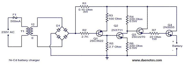
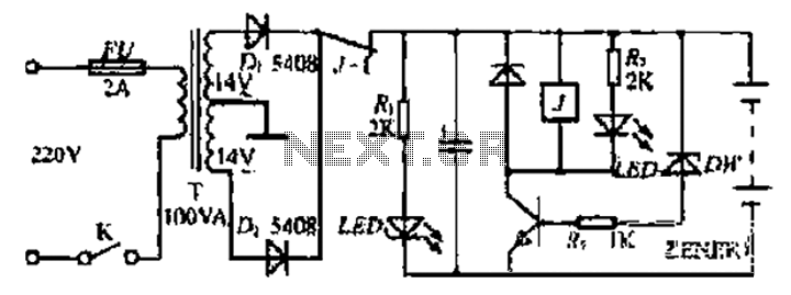
This circuit is primarily designed for charging 12V Ni-Cd battery packs. However, it can also be used to charge 6V and 9V battery packs with slight modifications. The circuit operates by utilizing a power supply that provides the necessary voltage...
For several years, a rear fog lamp has been mandatory for trailers and caravans to enhance visibility in foggy conditions. When this fog lamp is activated, the fog lamp of the towing vehicle must be turned off to prevent...
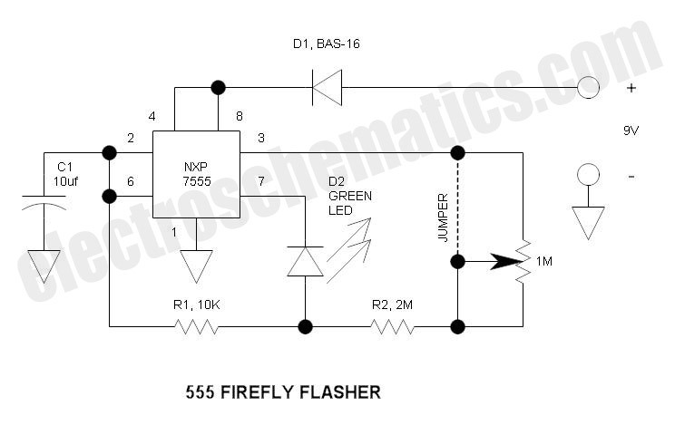
This circuit operates similarly to a standard 555 astable timer, with the distinction that the LED is integrated into the capacitor reset path. Consequently, when pin 7 discharges capacitor C1 to ground, a relatively high current flows through the...
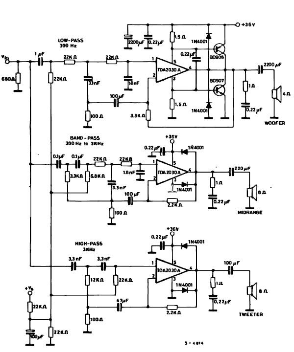
A simple multiway active speaker audio system can be designed using the TDA2030 audio IC. This TDA2030 active speaker audio system circuit is created to deliver optimal acoustic performance, as each loudspeaker is specifically designed and optimized for a...
The mixer can accommodate any number of channels as needed by duplicating the input sections illustrated in the schematic. One instance of this mixer featured 25 inputs. The mixer circuit is designed to provide flexibility in channel configuration, allowing for...
Warning: include(partials/cookie-banner.php): Failed to open stream: Permission denied in /var/www/html/nextgr/view-circuit.php on line 713
Warning: include(): Failed opening 'partials/cookie-banner.php' for inclusion (include_path='.:/usr/share/php') in /var/www/html/nextgr/view-circuit.php on line 713