
12V Low Cost Car Battery Charger Circuit PCB
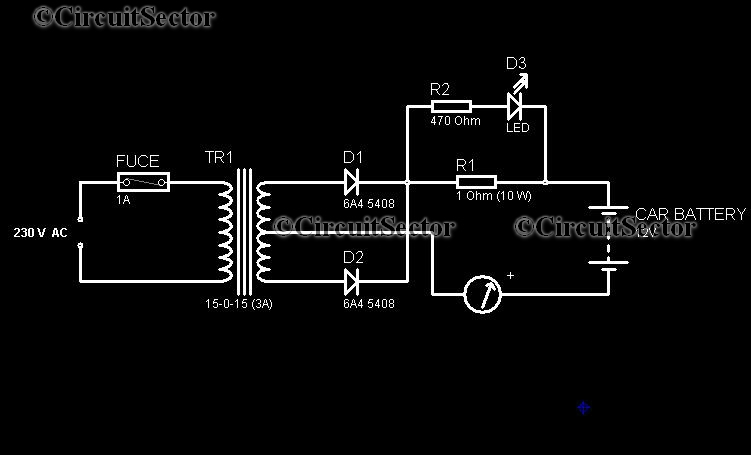
The described car battery charger circuit operates on a straightforward principle of converting AC voltage to DC, which is necessary for charging lead-acid batteries effectively. The center-tapped transformer steps down the mains voltage to a lower AC voltage, which is then rectified by diodes D1 and D2. These diodes are arranged to allow current to flow in one direction, producing a pulsating DC output.
The use of a 1-ohm wire-wound resistor serves a dual purpose. Primarily, it limits the current flowing into the battery, which is crucial for preventing damage due to overcharging. As the battery reaches its full charge, the charging current diminishes, approaching zero, which is indicated by the LED. The LED not only signifies that the circuit is active but also provides a visual cue regarding the charging status; a dim LED indicates a lower charging rate, while a brighter LED suggests that the battery is currently charging.
For those considering modifications, the circuit can be adapted for 24V batteries by adjusting the transformer turns ratio and ensuring that the diodes and resistor are rated for the increased voltage and current requirements. This flexibility makes the circuit suitable for a range of applications beyond just 12V systems.
In summary, this car battery charger circuit is an economical and efficient solution for maintaining vehicle battery health, ensuring that the battery remains charged and ready for use. Its simplicity and effectiveness make it a valuable addition to any home workshop or garage.Nowadays it has become necessary to own a car battery charger at home. By keeping one at home, we can avoid car starting trouble due to battery complaints. Buying one battery charger will cost you huge amounts while the components used in the car battery charger schematic is cheap. This charger circuit is designed for 12V car batteries, however we can tweak this circuit for a 24V charger. The charger circuit gives full wave rectified output voltage for charging lead acid batteries. The current reading become almost zero hen the battery is fully charged. the center tapped transformer, the diodes D1 and D2 constitute the unregulated supply portion. The One Ohm wire wound resistor of 10W connected in series controls the charging current and prevents the battery from overcharging. The LED shows the presence of the output voltage. Also its brightness depends on the charging rate. 🔗 External reference
Related Circuits
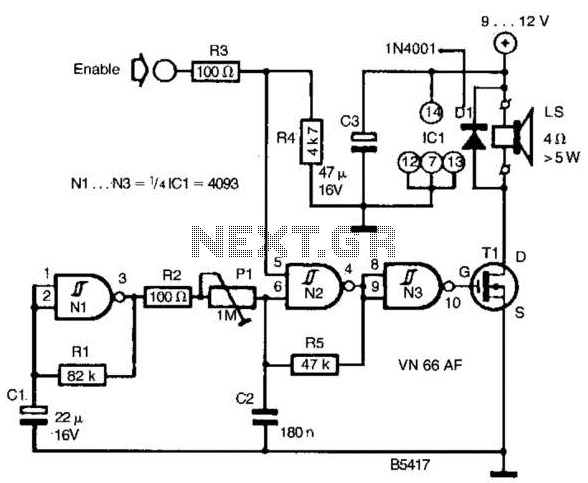
A CD4093 chip and several components form a siren oscillator that drives power MOSFET Tl. A speaker is directly powered by this device. The siren is activated by a logic high signal applied to the ENABLE input. The circuit comprises...
Inspect the work for potential dry joints, shorts across adjacent tracks, or soldering flux residues, as these often lead to issues. Recheck all external connections to and from the circuit for any mistakes. Ensure that all polarized components are...
This circuit utilizes two quad op-amps to create an eight LED audio level meter. The op-amp employed in this circuit is the LM324, a widely used integrated circuit that is readily available from numerous electronic component suppliers. The 1K...
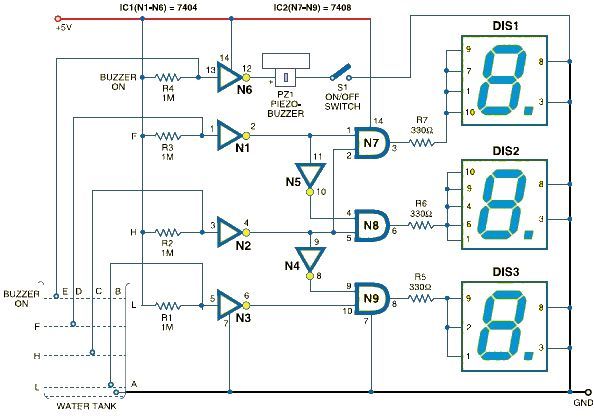
This schematic outlines a straightforward electronic project for designing a water level indicator circuit. It employs a 7-segment display to represent water levels in a tank as low, half, and full, indicated by the letters L, H, and F,...
The following circuit illustrates a Bluetooth-based smart home circuit diagram. This circuit is based on the ULN2003 integrated circuit (IC). Features include an LCD and LED. The Bluetooth-based smart home circuit utilizes the ULN2003 IC, which is a high-voltage, high-current...
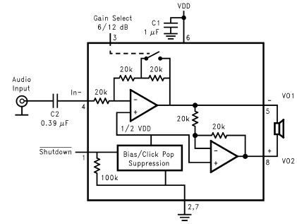
The LM4096 audio amplifier circuit diagram represents a straightforward audio amplifier capable of delivering a maximum output power of 1 watt, utilizing a minimal number of external electronic components. The LM4906, an audio power amplifier, is specifically engineered for...