
12V to +/- 20V DC Converter Circuit
The DC to DC converter circuit operates by utilizing the TL494 IC, which is well-regarded for its versatility in managing power supply applications. The adjustable frequency capability enables fine-tuning of the PWM signal, allowing for optimal performance based on the load requirements. The output voltage can be finely controlled to ensure that the desired +/-20 V DC is achieved, making this converter suitable for various applications where specific voltage levels are necessary.
The TL494's PWM output controls the switching of the MOSFETs, which are essential for the conversion process. The TPS2811P driver is specifically chosen for its ability to efficiently drive the MOSFETs, ensuring that they switch on and off quickly to minimize losses and improve overall efficiency. The use of two MOSFET transistors in the inverter stage allows for a push-pull configuration, which is beneficial for generating a symmetrical output voltage.
In practical applications, the circuit may include additional components such as inductors for energy storage, capacitors for filtering, and diodes for rectification, depending on the specific design requirements. The layout of the circuit should be carefully considered to minimize electromagnetic interference (EMI) and optimize thermal management, especially in high-power scenarios. The final output stage may also include feedback mechanisms to monitor and regulate the output voltage, ensuring stability under varying load conditions. Overall, this DC to DC converter circuit is a robust solution for applications requiring precise voltage regulation and high efficiency.DC To DC Converter circuit used to be an convert voltage DC to DC with different concepts. DC to DC converter circuit +12 V to + /-20V is working to change the battery voltage from 12V DC to 20V DC voltage symmetrical. DC to DC converter circuit is often applied to the power amplifier udio on car audio systems. DC to DC converter circuit uses a TL 494 IC as power plsa for the converter. TL494 IC is a PWM controller with an adjustable frequency from 40-60Hz through a potentiometer. Then from the TL494 PWM signal is given to the driver MOSFET inverter TPS2811P to be given to the power inverter with 2 units of MOSFET transistors. Circuit details can be seen in the figure following the DC to DC converter. 🔗 External reference
Related Circuits
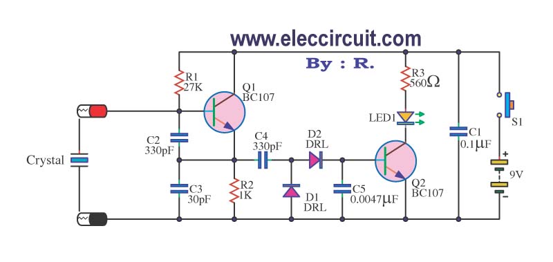
A multimeter cannot be used to test a crystal oscillator. Instead, a dedicated circuit is required, capable of checking crystals within the frequency range of 100 kHz to 900 MHz. This circuit is easy to construct and cost-effective. To construct...
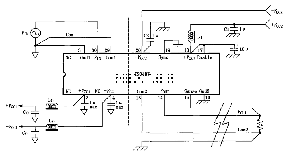
The basic connection circuit for the ISO107 signal and power supply is illustrated. Each power supply terminal must include a bypass filter. If the output current from the isolated power supply exceeds 15 mA, it is advisable to utilize...
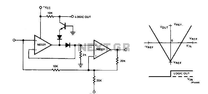
The cyclic converter is composed of a series of identical stages, each stage detecting the polarity of the input. The reference voltage, V_REF, is subtracted from the double entry, and the remaining value is processed if the polarity is...
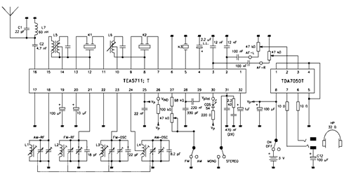
The TEA5711 datasheet indicates that essential functions, including the AM and FM front end, AM detector, and FM stereo output stages, are integrated within the TEA5711 AM/FM stereo radio circuit. The accompanying circuit diagram illustrates the TEA5711T in conjunction...
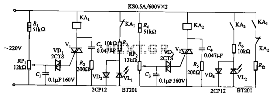
Bidirectional thyristor control. By adjusting potentiometers RPi and RPz, the lower and upper limit values can be changed. LEDs VLi and VL2 serve as indicators for low pressure and high pressure, respectively. The circuit utilizes a bidirectional thyristor to control...
Switch S2 is used for increasing and switch S3 is used for decreasing the volume. Similarly, switches S4 and S5 are provided for second channel (right channel) volume control. Also, pin 14 of IC2 can be connected to IC...