
Cyclic A/D converter circuit
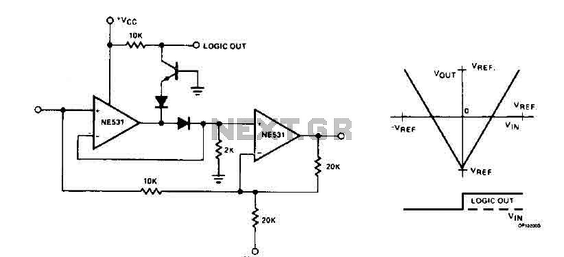
The cyclic converter operates by utilizing a modular design where each stage is responsible for determining the input signal's polarity. This detection is crucial for ensuring that the subsequent processing of the signal is accurate. When the input polarity is confirmed, the circuit performs a subtraction operation where the reference voltage (V_REF) is taken away from the doubled input value. This results in a modified signal that reflects the difference, which is then rectified using a full-wave rectification method. Full-wave rectification is essential as it allows for the conversion of both halves of the input waveform into a usable output, thus improving the efficiency of the signal processing.
The doubling of the difference between V_IN and V_REF enhances the sensitivity of the converter, allowing it to detect smaller changes in the input signal. The output of the converter is then formed into a gray code representation, which is a binary numeral system where two successive values differ in only one bit. This characteristic is particularly useful in applications requiring minimal error during the transition between values, as it reduces the chances of misreading the input due to simultaneous changes in multiple bits.
In practical applications, the NE531 devices are employed within the circuit to facilitate the necessary operations of voltage detection and processing. These devices are known for their precision and reliability, contributing to the overall performance of the cyclic converter. The combination of multiple stages, rectification, and the use of advanced components allows for high-accuracy voltage measurements and conversions, making this circuit suitable for various electronic applications where precise analog-to-digital conversion is required.The cyclic converter consists of a chain of identical stages, each of which detects the polarity of the input. Step V REF then subtracted from the double entry and the rest if the polarity is correct. The signal is full wave rectified and the rest of V IN - V REF is doubled. A string of these steps provides the equivalent gray code input voltage digital form related to the magnitude of V REF 'accuracy with high potential, the circuit using NE531 devices installed. 🔗 External reference
Related Circuits
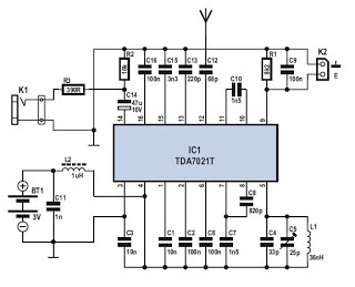
Several integrated circuits (ICs) are currently available that provide a nearly complete FM receiver solution. This project outlines a complete FM receiver circuit that offers excellent receiving and sound qualities. However, from a DIY enthusiast's perspective, the only drawback...
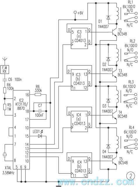
The remote control transmitter consists of a DTMF generator and an FM transmitter circuit. A UM91214B phone-specific integrated circuit (IC) is utilized to generate the DTMF signal, with a 3V power supply provided by a 3V zener diode (D1)....
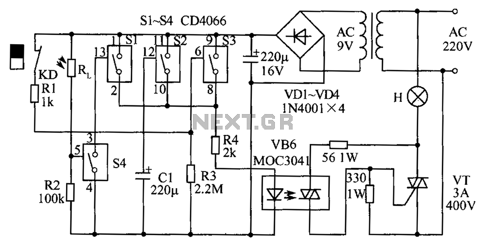
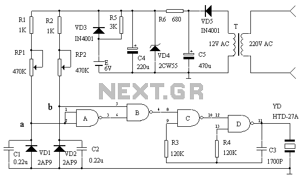
The circuit diagram illustrates a group of four analog electronic circuit switches (S1 to S4). Switches S1, S2, and S3 are utilized in a parallel delay circuit. When the power is activated, resistor R4 drives the triac VT, which...
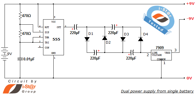
How to create a dual power supply unit using a single battery for laboratory purposes. Dual voltage power supplies are particularly needed for operational amplifier experiments and some instrumentation amplifiers. Additionally, certain low-power audio preamplifiers also require dual voltage...
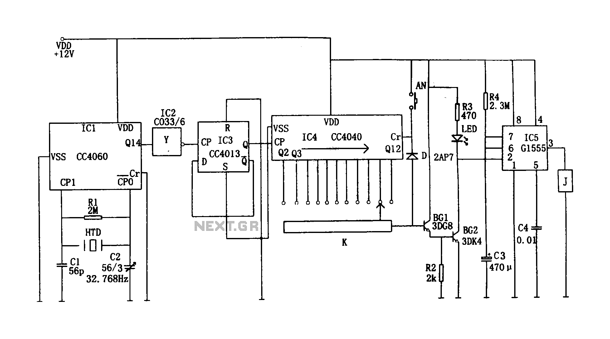
This circuit illustrates a precision digital timing control system. The controller includes a crystal oscillator circuit, a divider, a counting circuit, and monostable flip-flops. The crystal oscillator circuit features a series of 14 binary counters/dividers, a watch crystal operating...
This circuit serves as an over-temperature alarm and cooling system utilizing CD4011 four NAND gate integrated circuits to monitor the oven's temperature. In the event of a thermostat circuit failure or power outage, if the internal temperature exceeds or...