
12V to 3V convertor

This 12V to 3V converter circuit typically employs a linear voltage regulator, such as the LM317 or a similar adjustable regulator, which is capable of providing a stable output voltage by dissipating excess voltage as heat. The input voltage of 12V is fed into the regulator, where it is reduced to the desired output voltage of 3V.
The circuit consists of the following key components:
1. **Voltage Regulator**: An LM317 adjustable voltage regulator is commonly used. It has three terminals: input, output, and adjustment. The output voltage can be set by using two resistors in a voltage divider configuration, which connects to the adjustment terminal.
2. **Input Capacitor**: A capacitor (typically 0.1µF) is placed at the input of the regulator to filter out high-frequency noise from the power supply, ensuring stable operation.
3. **Output Capacitor**: A larger capacitor (usually 10µF or greater) is connected at the output to improve transient response and provide stability to the output voltage.
4. **Resistors**: Two resistors are used to set the output voltage. The values of these resistors can be calculated using the formula provided in the LM317 datasheet, which relates the output voltage to the ratio of the resistors.
5. **Heat Sink**: Since the LM317 can dissipate a significant amount of heat when dropping from 12V to 3V, a heat sink is recommended to prevent overheating and ensure reliable operation.
6. **Protection Diodes**: Including a diode across the output can protect against reverse polarity and transient voltage spikes, enhancing the circuit's robustness.
This circuit is particularly useful in applications where a low voltage is required from a higher voltage supply, such as powering sensors, microcontrollers, or other low-voltage devices. The simplicity and low cost of the components make it an ideal choice for hobbyists and in educational settings for demonstrating basic voltage regulation principles.12V to 3V convertor. This is an simple and cheap circuit to convert voltage from 12V to 3V.In fact this is a basic regulator circuit.
Related Circuits
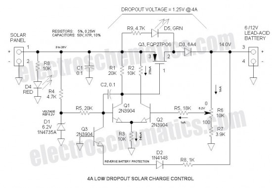
This Low Dropout Voltage (LDO) solar charge controller utilizes a straightforward differential amplifier combined with a series P-channel MOSFET linear regulator, creating an effective synergy. The voltage output is adjustable and is primarily designed for charging 12V lead-acid batteries....
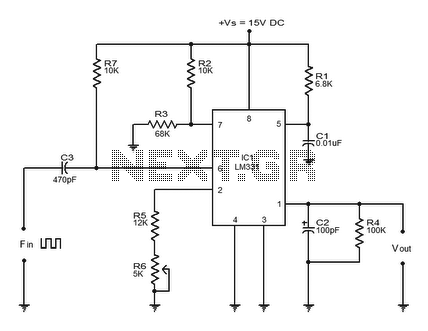
Converter circuits are commonly utilized in various applications, and there are several types available. A simple frequency-to-voltage converter circuit uses the IC LM331, which is essentially a precision voltage-to-frequency converter. This IC has numerous applications, and in this instance,...
This circuit will generate a smaller DC output voltage from a larger DC input voltage. It is quick and simple to make and by changing the value of the zener diode, the circuit can be universally adapted to provide...
This circuit converts 12V DC into 220V AC. It utilizes a 4047 integrated circuit to generate a 50Hz square wave, which is then used to amplify the current and subsequently increase the voltage using a step-up transformer. The circuit...
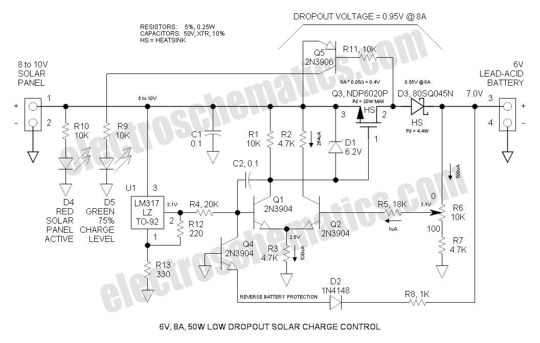
This Low Dropout Voltage (LDO) solar charge controller utilizes a straightforward differential amplifier combined with a series P-channel MOSFET linear regulator, ensuring compatibility and efficiency in solar energy applications. The Low Dropout Voltage (LDO) solar charge controller is designed to...
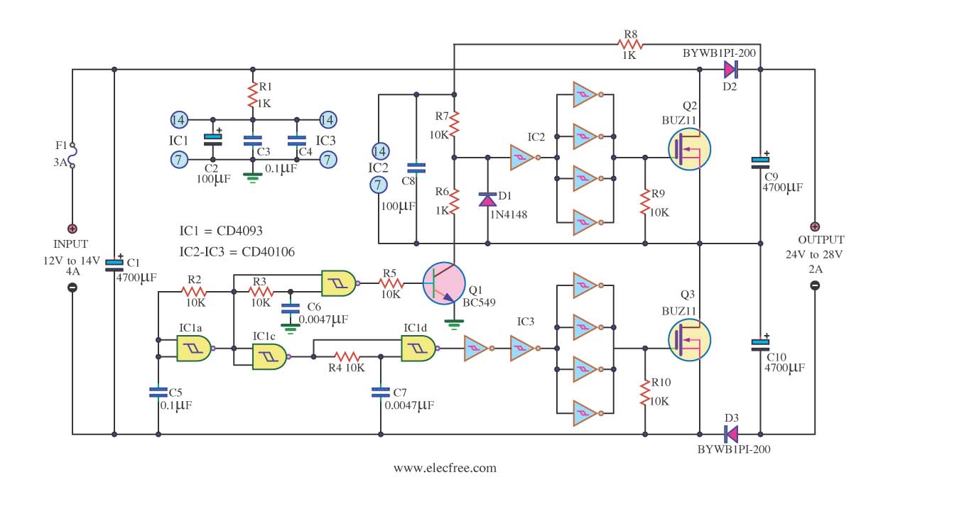
This is a DC to DC converter circuit designed to take an input of 12V to 24V at 4A and convert it to an output of 24V to 48V at 2A. The circuit utilizes simple components, including a CMOS...