
DC/DC Converter DC12V to 24V 2A by IC 40106 and Mosfet BUZ11

The DC to DC converter circuit operates by stepping up the input voltage while regulating the output to the desired levels. The primary component, the 40106 CMOS IC, functions as a Schmitt trigger oscillator, which generates a square wave signal. This square wave is essential for driving the MOSFET, which acts as a switch in the circuit.
The input voltage range of 12V to 24V allows for flexibility in power supply options, while the 4A input current capability ensures that the circuit can handle substantial loads. The output voltage can be adjusted between 24V and 48V, making it suitable for various applications requiring higher voltage levels.
The MOSFET in this design is responsible for switching the current through the inductor, which stores energy during the ON phase of the MOSFET and releases it during the OFF phase. This process is crucial for stepping up the voltage. The choice of MOSFET is critical; it must have low on-resistance to minimize power losses and a suitable voltage rating to handle the output voltage requirements.
Additional passive components, such as inductors, capacitors, and diodes, are also integral to the circuit. The inductor value must be selected to ensure efficient energy transfer, while the capacitors smooth out the output voltage and filter any ripple caused by the switching action. A diode is typically used in the output stage to prevent backflow of current, ensuring the stability and reliability of the output voltage.
Overall, the described DC to DC converter circuit is an effective solution for applications requiring voltage conversion with moderate power levels, utilizing readily available electronic components for ease of implementation.This is Circuit DC to DC Converter. For input DC12V-24V 4A to Output 24V-48V 2A (inputX2) Use easy circuit simple part IC Digital Cmos : 40106 and Mosfet.. 🔗 External reference
Related Circuits
This is a 100-watt inverter circuit diagram. It is built using the IC CD4047 and the MOSFET IRF540. This inverter has the capability to supply electronic devices that require 220VAC, with a maximum output of 100 watts from a...
The simplest current-to-voltage (I to V) converter is a basic resistor. However, the disadvantage of this simple configuration is that it presents a nonzero impedance to the input current source. The I to V converter is an essential circuit in...
The ML7005 is a multi-functional DTMF transceiver LSI that incorporates a DTMF signal generator, a DTMF signal receiver, a call progress tone generator, a call progress tone detector, and a FAX (FX) signal detector. Each functional block can be...
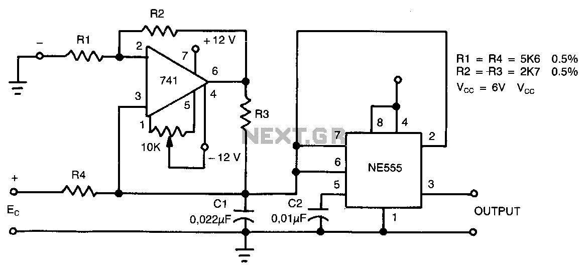
This circuit can accept positive, negative, or differential control voltages. The output frequency is zero when the control voltage is zero. The 741 operational amplifier forms a current source controlled by the voltage Ec to charge the timing capacitor...
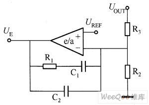
The on-off type DC/DC converter operates in two modes. One mode maintains a constant duty cycle for the switch, while the other varies the pulse frequency modulation (PFM) while keeping the on-time constant. The pulse width modulation (PWM) DC/DC...
The circuit is a temperature-to-pulse-width converter. The LM3524 is used to convert the output of an LM135 temperature transducer into a pulse width that can be measured by a digital system, such as a microprocessor-controlled data acquisition system. In...