
12vdc 220vac inverter using cmos cd4047

The inverter circuit utilizing the CMOS 4047 offers a robust solution for converting low-voltage DC power to high-voltage AC power, making it suitable for various applications such as powering household appliances or for use in renewable energy systems. The CMOS 4047 is configured as an astable multivibrator, which generates a continuous square wave output. This output is crucial for driving the subsequent amplification stage.
The use of Darlington transistors T1 and T2 serves to significantly increase the current output of the circuit, allowing for effective driving of the transformer. These transistors are known for their high current gain, which ensures that the signal from the 4047 can be amplified sufficiently to drive the transformer without distortion.
The transformer plays a critical role in stepping up the voltage from the secondary coil. The specification of the transformer as 2 x 10V/1 indicates that it is designed for a specific winding configuration, which allows it to handle the required power rating. The choice of a toroidal core transformer is advantageous due to its efficiency and reduced electromagnetic interference, which contributes to overall performance improvement by minimizing losses during operation.
Furthermore, the inclusion of a potentiometer, P1, for frequency adjustment allows for flexibility in the output frequency, catering to different application requirements. The ability to vary the frequency from 50 Hz to 400 Hz offers versatility, enabling the inverter to be tailored for specific devices that may operate at different frequencies. This feature is particularly useful in applications where precise frequency control is necessary for optimal performance.
Overall, this inverter circuit design is efficient, adaptable, and capable of providing a reliable source of AC power from a DC input, making it a valuable component in modern electronic systems.The inverter circuit has a central component, the CMOS 4047, and converts a 12V DC voltage to 220V AC voltage. 4047 is utilised as a astable multivibrator. At pin 10 and 11 we find a rectangular symmetrically signal which is amplified by tow Darlington transistors T1 and T2 and finally reaches the secondary coil of a transformer network (2 x 10V/1
00VA). Primary coil terminals voltage is 220 alternative voltage. To obtain a better performance use a toroidal core transformer with reduced losses. With P1 the output frequency can be regulated between certain limits (50 400Hz). 🔗 External reference
Related Circuits
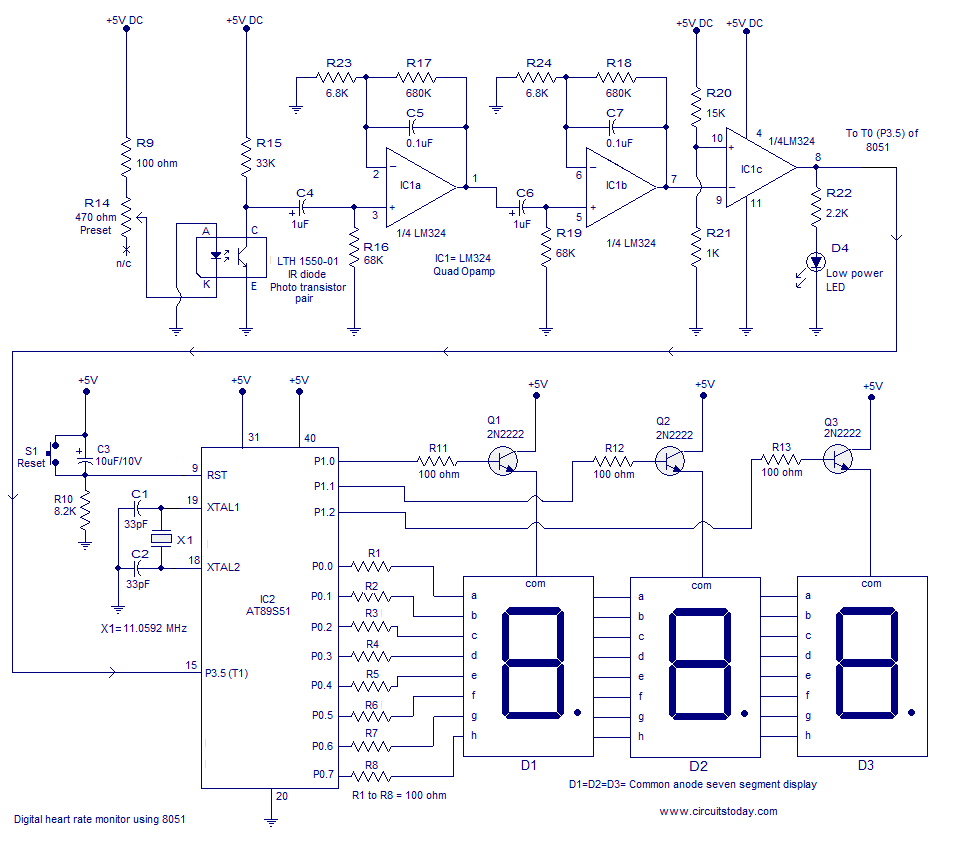
Heart rate monitor using an 8051 microcontroller. It measures the heart rate from the fingertip using an IR diode and phototransistor pair (Photoplethysmography). The AT89S51 microcontroller is utilized in this application. The heart rate monitor circuit operates based on the...

The project involves SMS control for older Nokia phones using the FBUS protocol, which is a complex communication method requiring detailed understanding and coding. The author has successfully implemented this project using an 89S52 microcontroller with only 256 bytes...
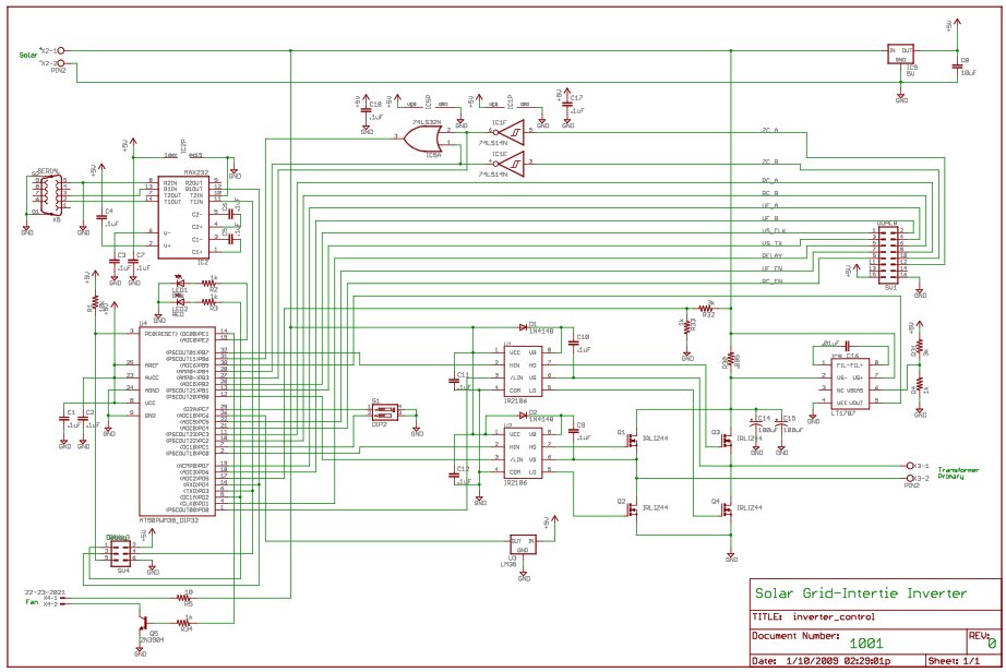
For the last year, a prototype for a solar inverter that can be grid-intertied has been developed. A solar inverter converts 12V DC (or other voltages) from solar panels. The solar inverter is a crucial component in photovoltaic systems, responsible...
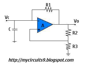
This circuit is also known as a Free Running Oscillator because it does not require any trigger pulse to become active. Consider the moment when Vc equals +Vsat. At this point, the capacitor charges exponentially towards +Vsat through resistor...
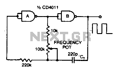
Adjusting the 100 K ohm potentiometer modifies the discharge rate of capacitor Ct, thereby affecting the output frequency. A square wave output is produced. The maximum frequency achievable with CMOS technology is constrained to 2 MHz. The circuit described involves...
The output of this circuit is push-pull and consumes less than 3 mA (with no signal) but drives the earpiece to a very loud level when audio is detected. This circuit operates in a push-pull configuration, which allows it to...