
Small Amplifier Using Transistors
This circuit operates in a push-pull configuration, which allows it to efficiently drive an earpiece or speaker with minimal power consumption. The quiescent current draw is less than 3 mA when idle, indicating a low-power design that is suitable for battery-operated devices. The push-pull arrangement utilizes complementary transistors or amplifying devices to amplify the audio signal while maintaining a balanced output.
When an audio signal is detected, the circuit dynamically adjusts to deliver a significant output power to the earpiece, producing a loud sound. This capability is particularly beneficial in applications where high audio output is required from a compact and energy-efficient circuit.
The design may include additional components such as capacitors for coupling and bypassing, resistors for biasing, and possibly feedback mechanisms to stabilize the gain and ensure linearity in audio reproduction. The circuit's topology may also feature protection elements to prevent damage from overcurrent conditions or to filter out unwanted noise, ensuring a clear audio signal is delivered to the earpiece.
Overall, this circuit exemplifies an effective solution for applications requiring high audio output with minimal power consumption, making it ideal for portable audio devices.The output of this circuit is push-pull and consumes less than 3mA (with no signal) but drives the earpiece to a very loud level when audio is detected.. 🔗 External reference
Related Circuits
Water is a valuable resource in many regions, with numerous individuals depending on water tanks to enhance their water supply by storing collected rainwater or water drawn from a well or bore. Measuring the fullness of a tank can...
The following segment provides the enhanced Motorola schematic for a typical application of the MRF141G, which includes parasitic stabilization features. The MRF141G is a broadband power RF MOSFET capable of delivering a conservatively rated 300 watts across the FM...

This circuit diagram of a digital clock utilizes six common anode seven-segment displays to indicate the time. It does not require microcontrollers or PICs for operation. The circuit operates using the MM5314 integrated circuit, functioning at either 50 Hz...

The multifunction frequency meter is an instrument that can measure various parameters on a single display using an 8-digit 7-segment LED. The controls measure... The multifunction frequency meter is designed to provide accurate measurements of frequency, voltage, current, and other...
Figure A illustrates the schematic of a microstrip single-stage RF amplifier. This amplifier utilizes the M/A-Com LF2810A MOSFET, which is rated for 10 watts and operates at 28 volts, but it delivers sufficient gain for this application at a...
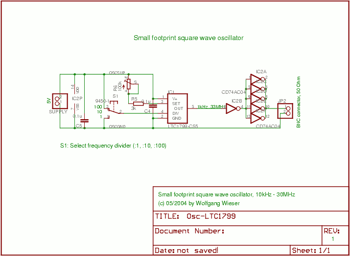
This is a compact square wave oscillator that operates at a 50% duty cycle, with a variable frequency ranging from 10 kHz to 30 MHz. The frequency range can be extended to 1 kHz by substituting a 1 MΩ...