
15-65MHz circuit diagram of the third harmonic
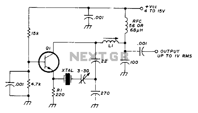
The circuit diagram focuses on enhancing the startup reliability of a crystal oscillator while maintaining low power consumption. The selection of transistors such as the 2N918, 2N3564, 2N5770, BF180, or BF200 allows for flexibility in performance characteristics, ensuring that the circuit can be tailored to specific application requirements.
The resonator's specifications indicate that it operates efficiently at two distinct frequency ranges, with the 22pF capacitance ensuring that the oscillator maintains stability across these frequencies. The inductor L1 plays a crucial role in tuning the oscillator circuit, allowing it to resonate at the desired frequencies of either 15-30MHz or 30-65MHz, depending on the selected inductance.
This design is particularly advantageous for applications requiring precise frequency generation with minimal power draw, making it suitable for battery-operated devices or energy-efficient systems. The combination of the chosen components facilitates a reliable oscillator that can maintain performance under varying operational conditions, thereby enhancing overall circuit reliability and efficiency.A circuit diagram of the crystal startup reliability, power consumption is much lower than the crystal maximum allowed. Q1 is 2N918,2N3564,2N5770, BF180 or BF200. L1 frequency crystal resonator is 22pF (15-30MHz, 1 H or 30-65MHz, 0.5 H). As good stability and the fundamental frequency oscillator.
Related Circuits
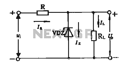
The simple voltage regulator circuit consists of a silicon regulator and a resistor. It is designed to rectify and filter DC voltage, as illustrated in the accompanying figure. The voltage regulator is connected in parallel with the load, and...

The DC motor E inversion control circuit utilizes a loop configuration with various relay contacts. It employs a single set of normally open/normally closed relay contacts. When both inputs A and B are low, relay KI is activated. In...
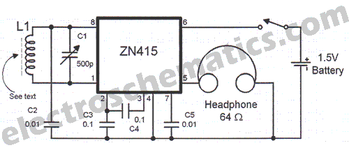
There are instances when a radio station can be found, and other times when no stations are detectable. The primary issue while tuning appears to be that any movement of the hands or body, such as releasing the tuning...
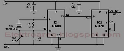
This circuit is designed for accurate time-base generation utilizing the commonly available 3.5795 MHz crystal, which is frequently used in telecommunication equipment. A crystal-based oscillator combined with a divider IC chain or a similar circuit, such as an ASIC,...
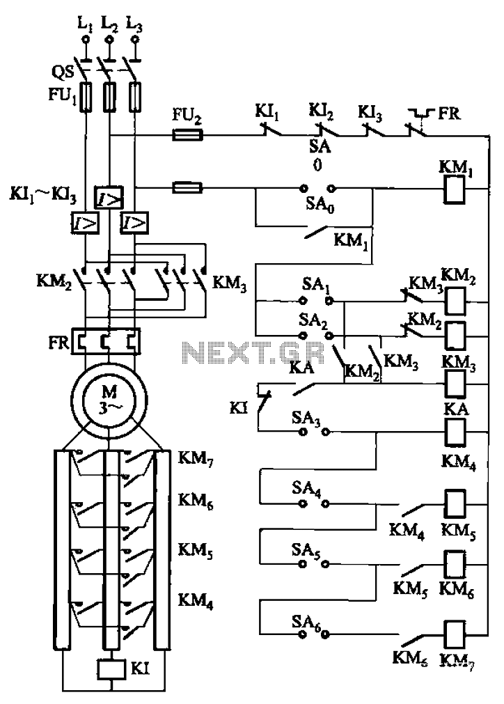
The circuit depicted in Figure 3-168 utilizes a controller for speed grading and reversing control. A reverse brake is connected to the rotor circuit through an overcurrent relay, labeled KI, for control. The current relay KIi to KI3 serves...
A programmable clock timer circuit that utilizes individual LEDs to indicate hours and minutes. Twelve LEDs can be arranged in a circle to represent the twelve hours of a clock face, while an additional twelve LEDs can be arranged...
Warning: include(partials/cookie-banner.php): Failed to open stream: Permission denied in /var/www/html/nextgr/view-circuit.php on line 713
Warning: include(): Failed opening 'partials/cookie-banner.php' for inclusion (include_path='.:/usr/share/php') in /var/www/html/nextgr/view-circuit.php on line 713