
Two models of DC motor reversing control circuit

The DC motor inversion control circuit is designed to allow for bidirectional control of a DC motor through the use of relay logic. The primary components include normally open (NO) and normally closed (NC) relay contacts that govern the operation of the motor based on the logic states of two control inputs, A and B.
In the initial state where both inputs are low (0V), relay KI is activated, allowing current to flow through the motor in one direction. This configuration is crucial for applications requiring a specific operational mode, such as water transfer mechanisms. As the circuit is designed, once input A transitions to a high state (5V), relay KI deactivates, which interrupts the motor's operation. This transition is essential for stopping the motor safely before changing its direction.
When input B is subsequently set to high, the circuit engages the relay contacts JK2 and JK32, which reverse the polarity applied to the motor terminals. This reversal is facilitated by the use of a reversing relay, which can be selected from a range of models such as 4088, 4098, or others, depending on the application's specific requirements.
The circuit also includes safeguards to prevent both inputs A and B from being high at the same time, which would create a short-circuit condition. When both inputs are low, relays JK1 and JK2 remain inactive, ensuring that the motor does not turn unintentionally. The design ensures that the motor can be stopped and reversed safely, which is critical for applications that require precise control over motor operation.
In summary, this DC motor E inversion control circuit provides a robust solution for controlling the direction of a DC motor through the strategic use of relay contacts, ensuring safe operation and flexibility in application.DC motor E inversion control circuit, the circuit loop L li KDL -. 80 (primer using a single set of normally open/normally record relay contacts when A.B two low, the relay KI, JK, JK ] surgery are turned on, the motor water transfer: a point for the business when the half-indole, relay contact point/KI 2 IE turn off motors when the B point a is high, the relay contacts fUKl 2.JKzI JK32. closed boat, motor the reversing relay IIr selection 4088. 4098.T70, T71, etc. secluded J -. 80 (b) for the introduction of two normally open/normally Chun relay contacts is low when A.B two semi relay when JKi, JKz does not move, the motor does not turn when the point a is high relay contacts jkl :./Ki 4 off, the motor positive and negative: when the B point is high, the relay contacts JK2 BU/K2 4 is closed, the motor the reversing ripple Italy should foot: B points can not be both a high-level relay can be used 1ZC 7F.
4099 et al.,
Related Circuits
This is a VU meter circuit featuring 10 LEDs. This simple LED VU meter consists of only a few components, yet it serves as an effective indicator for sound levels. The circuit is constructed around an unspecified component. The VU...
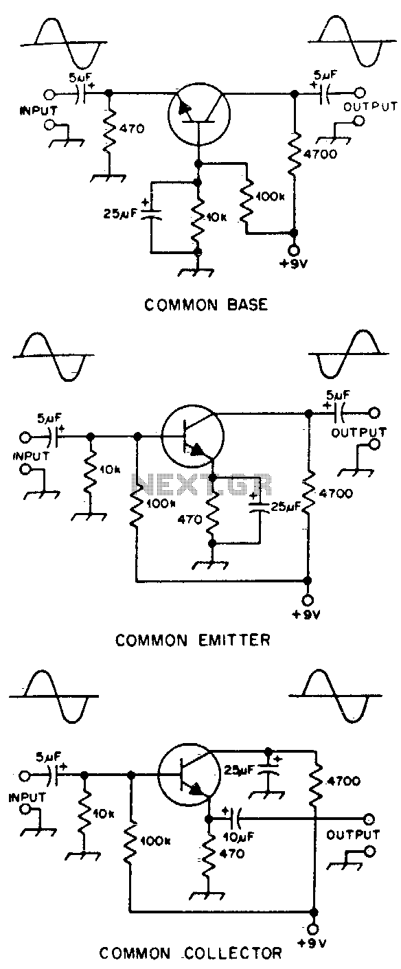
Typical component values are provided for use at audio frequencies, where these circuits are most commonly utilized. The input and output phase relationships are illustrated. The circuit design focuses on audio frequency applications, emphasizing the selection of component values that...
This circuit turns off an amplifier or any other device when it remains idle for 15 minutes. It is powered by the amplifier's tape output. The described circuit functions as an automatic power management system, designed to enhance energy efficiency...
A simple square wave oscillator can be created using two gates from a CMOS 4011 NAND chip. Alternatively, a CMOS 4001 chip or a TTL equivalent can also be utilized. In this circuit, the mark-space ratio can be independently...
Writing assembly code for microcontrollers (MCUs) can often be a challenging and time-consuming process. However, software development can be streamlined, allowing more time for electronics hardware design by utilizing TINA's Flowchart editor and debugger. This tool enables the generation...
This circuit utilizes a sawtooth oscillator along with an output amplifier that drives a transistor. The components C1, C2, and L1 are essential for the oscillator's operation, forming a tank circuit that must be tuned to the resonant frequency....