
15 Watt Amplifier

This 15-watt amplifier circuit is constructed using discrete components, which allows for greater flexibility in design and optimization compared to integrated circuits. The amplifier is powered by a dual 20-volt power supply, which provides the necessary voltage headroom for efficient operation and ensures that the amplifier can deliver up to 15 watts RMS into an 8-ohm load, making it suitable for driving speakers in various audio applications.
The core of the amplifier is a common emitter configuration utilizing transistor Q1. This configuration is known for its ability to provide significant voltage gain, which is essential for amplifying weak audio signals. The input signal is fed into the base of Q1, where it is amplified before being sent to the output stage. The biasing of Q1 is critical for its operation, and this is managed by a bias chain that includes transistors Q8 and Q9, as well as diodes D6, D13, and D14.
Transistors Q8 and Q9 are configured to provide a constant current source, which stabilizes the operating point of Q1 across varying load conditions and temperature fluctuations. This constant current configuration helps to minimize distortion and improve linearity in the amplifier's performance. The diodes in the bias chain serve to provide temperature compensation, ensuring that the bias point remains stable even as the circuit heats up during operation.
The output stage of the amplifier is designed to drive an 8-ohm load effectively, delivering the specified 15 watts RMS. The choice of components, including the transistors and diodes, should be made with consideration of their thermal characteristics and power ratings to ensure reliable operation under maximum load conditions.
Overall, this amplifier design exemplifies a practical application of discrete component circuitry in audio amplification, showcasing the principles of transistor operation, biasing techniques, and thermal management in electronic circuit design.A 15 watt amplifier made using discrete components. Sergio designed this circuit for his Electronics Level II course. This amplifier uses a dual 20 Volt power supply and delivers 15 watts RMS into an 8 ohm load. Q1 operates in common emitter, the input signal being passed to the bias chain consisting of Q8, Q9, D6, D13 and D14. Q8 and Q9 provide a constant current throug 🔗 External reference
Related Circuits
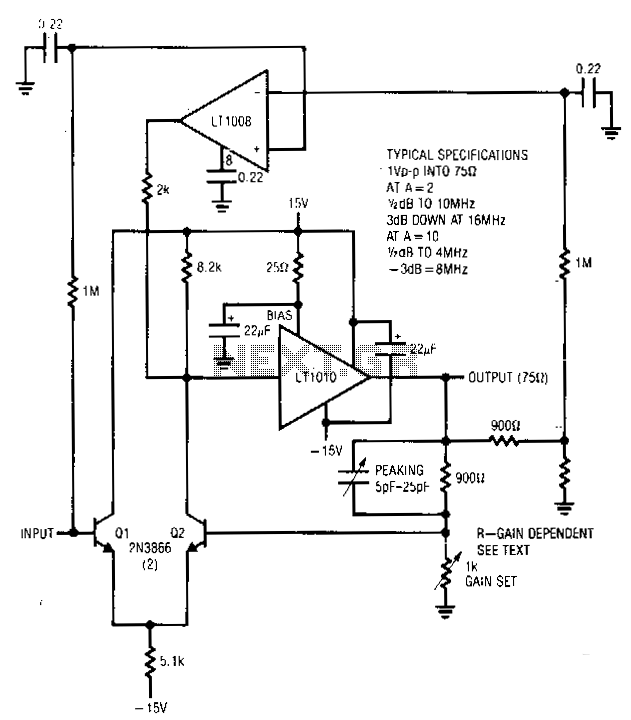
This amplifier operates across a broad range of gains, typically from 1 to 10. It integrates the LT1010 with a fast discrete stage and an LT1008-based destabilizing loop. Transistors Q1 and Q2 create a differential stage that converts to...
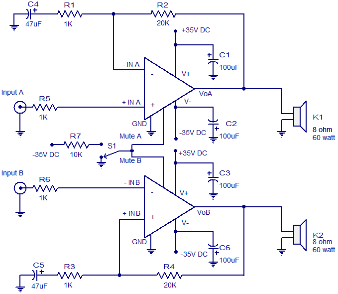
The circuit diagram presented is for a 2 x 60 Watt stereo amplifier utilizing the LM4780 from National Semiconductors. The LM4780 is an excellent audio amplifier integrated circuit capable of delivering 60W RMS power output per channel into 8-ohm...
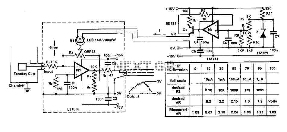
To amplify small current signals as an electron collector inside a vacuum chamber, it is advantageous for reasons related to noise and bandwidth to have a "head-amplifier" connected to the chamber. Operational amplifier 1 is a precision device featuring...
To complement the 60 Watt MOSFET audio amplifier, a high-quality preamplifier design was necessary. A discrete components topology using +24V and -24V supply rails was chosen, minimizing the transistor count while still achieving low noise, very low distortion, and...
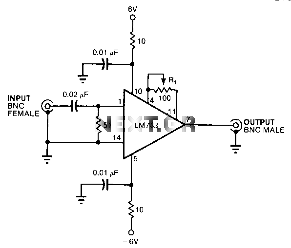
This circuit provides a voltage gain of 20 ±0.1 dB from 0.5 to 25 MHz and ±3 dB from 70 kHz to 55 MHz. An LM733 video amplifier offers a low input noise specification, with a typical value of...
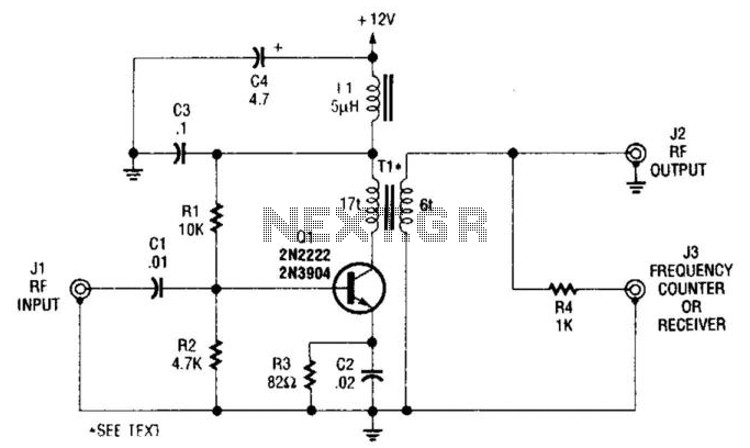
This single-stage amplifier, utilizing a 2N2222 or 2N3904 general-purpose transistor, is designed for interfacing with test instruments. The transformer T1 is an Amidon Associates FT-23-43 core, wound with 17 turns of #26 wire for the primary and 6 turns...