
Moduler PreamplifierCircuit
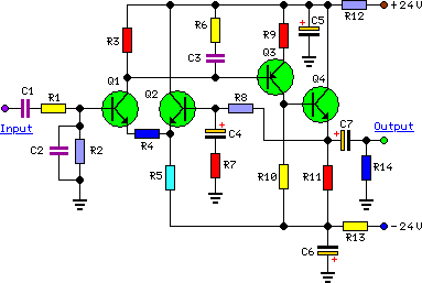
The preamplifier circuit is designed to enhance the audio signal quality before amplification. The discrete component design minimizes noise and distortion, ensuring a high fidelity audio experience. The use of a dual power supply allows for balanced operation, which is critical in audio applications to reduce hum and noise. The modular approach enables flexibility in configuration, allowing the user to customize input options based on their specific audio sources.
The main module serves as the core of the preamplifier, with careful attention paid to the op-amp configuration and resistor values to optimize performance. The inclusion of a changeover switch facilitates easy switching between multiple audio sources, ensuring versatility for the user. The output stage, which interfaces with the power amplifier, is designed to maintain signal integrity while providing adequate driving capability.
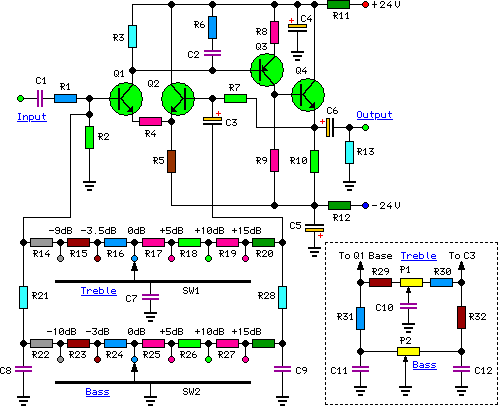
The tone control module enhances the functionality of the preamplifier by allowing users to tailor the audio output to their preferences. The innovative use of rotary switches instead of traditional potentiometers offers precise control over bass and treble frequencies, addressing common issues with channel matching in stereo setups. The asymmetrical configuration of the tone control settings reflects practical usage patterns, focusing on boosting frequencies rather than cutting them.
Power supply design is critical for the overall performance of the preamplifier. The recommended transformer and rectification method ensure stable voltage levels necessary for optimal operation. The inclusion of IC regulators further stabilizes the power supply, providing clean DC voltage to the preamplifier circuits.
For safety, especially in standalone applications, the incorporation of output short-circuit protection is essential. The series resistor serves as a safeguard against potential shorts, protecting both the preamplifier and the connected power amplifier from damage. Overall, this preamplifier design combines functionality, flexibility, and performance, making it suitable for a variety of audio applications.To complement the 60 Watt MosFet Audio Amplifier a High Quality Preamplifier design was necessary. A discrete components topology, using + and - 24V supply rails was chosen, keeping the transistor count to the minimum, but still allowing low noise, very low distortion and high input overload margin. Obviously, the modules forming this preamplifier can be used in different combinations and drive different power amplifiers, provided the following stages present a reasonably high input impedance (i. e. higher than 10KOhm). If a Tone Control facility is not needed, the Preamplifier will be formed by the Main Module only. Its input will be connected to some sort of changeover switch, in order to allow several audio reproduction devices to be connected, e.
g. CD player, Tuner, Tape Recorder, iPod, MiniDisc etc. The total amount and type of inputs is left to the choice of the home constructor. The output of the Main Module will be connected to a 22K Log. potentiometer (dual gang if a stereo preamp was planned). The central and ground leads of this potentiometer must be connected to the power amplifier input. This Module employs an unusual topology, still maintaining the basic op-amp circuitry of the Main Module with a few changes in resistor values. A special feature of this circuit is the use of six ways switches instead of the more common potentiometers: in this way, precise "tone flat" setting, or preset dB steps in bass and treble boost or cut can be obtained.
Tone Control switches also allow a more precise channel matching when a stereo configuration is used, avoiding the frequent poor alignment accuracy presented by common ganged potentiometers. Six ways (two poles for stereo) rotary switches were chosen for this purpose as easily available. This dictated the unusual "asymmetrical" configuration of three positions for boost, one for flat and two for cut.
This choice was based on the fact that tone controls are used in practice more for frequency boosting than for cutting purposes. In any case, +5dB +10dB and +15dB of bass boost and -3dB and -10dB of bass cut were provided. Treble boost was also set to +5dB +10dB and +15dB and treble cut to -3. 5dB and -9dB. Those wishing to use common potentiometers in the usual way for Tone Controls may use the circuit shown enclosed in the dashed box (bottom-right of the Tone Control Module circuit diagram) to replace switched controls.
The Tone Control Module should usually be placed after the Main Input Module, and the volume control inserted between the Tone Control Module output and the power amplifier input. Alternatively, the volume control can also be placed between Main Input Module and Tone Control Module, at will.
Furthermore, the position of these two modules can be also interchanged. The preamplifier must be feed by a dual-rail, +24 and -24V 50mA dc power supply. This is easily achieved by using a 48V 3VA center-tapped mains transformer, a 100V 1A bridge rectifier and a couple of 2200 µF 50V smoothing capacitors. To these components two 24V IC regulators must be added: a 7824 (or 78L24) for the positive rail and a 7924 (or 79L24) for the negative one.
The diagram of such a power supply is the same of that used in the Headphone Amplifier, but the voltages of the secondary winding of the transformer, smoothing capacitors and IC regulators must be uprated. Alternatively, the dc voltage can be directly derived from the dc supply rails of the power amplifier, provided that both 24V regulators are added.
If this preamplifier is used as a separate, stand-alone device, thus requiring a cable connection to the power amplifier, some kind of output short-circuit protection is needed, due to possible shorts caused by incorrect plugging. The simplest solution is to wire a 3K3 1/4W resistor in series to the output capacitor of the last module (i.
e. the module having its output connected to the preamp main output socket). 🔗 External reference
Related Circuits

High-quality, discrete component design for input and tone control modules to complement the 60-watt MOSFET audio amplifier with a high-quality preamplifier design. The circuit design focuses on creating a high-fidelity audio preamplifier that enhances the performance of a 60-watt MOSFET...

This module utilizes an unconventional topology while retaining the fundamental operational amplifier circuitry of the main module, with some modifications in resistor values. A distinctive feature of this circuit is the incorporation of six-way switches instead of the more...
To complement the 60 Watt MOSFET audio amplifier, a high-quality preamplifier design was necessary. A discrete component topology, utilizing +24V and -24V supply rails, was selected, minimizing the transistor count while ensuring low noise, very low distortion, and a...
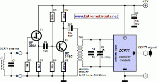
DCF77 Preamplifier Circuit Diagram A popular project among microcontroller enthusiasts is to build a radio-controlled clock. Small receiver boards are available, equipped with a pre-adjusted ferrite antenna, that receive and demodulate the DCF77 time signal broadcast from Mainflingen in...

To complement the 60 Watt MOSFET Audio Amplifier, a high-quality preamplifier design was necessary. A discrete component topology, utilizing ±24V supply rails, was chosen, maintaining a minimal transistor count while still achieving low noise, very low distortion, and a...

To complement the 60 Watt MOSFET audio amplifier, a high-quality preamplifier design was necessary. A discrete components topology utilizing ±24V supply rails was selected, with an emphasis on minimizing the transistor count while achieving low noise, very low distortion,...