
15 Watt switching power supply
The 15 Watt switching power supply circuit operates by utilizing a pulse-width modulation (PWM) technique, which is essential for regulating the output voltage and current efficiently. The TL494 integrated circuit serves as the heart of the PWM controller, managing the switching frequency and duty cycle to optimize the power conversion process. This design allows for a compact and lightweight power supply solution, making it suitable for applications where space is limited.
The pulse transformer T1 plays a crucial role in transferring energy from the primary side to the secondary side while providing electrical isolation. The choice of ferrite core material, such as M2500NMS-2 or M2000NM9, ensures high efficiency and minimal losses during operation. The winding configuration, with specific turns of different wire gauges, is designed to achieve the desired inductance and impedance matching for optimal performance.
In terms of output capabilities, the power supply can deliver stable voltage levels suitable for various electronic devices, including audio amplifiers and other consumer electronics. The ability to handle input voltages of up to 40,000 volts highlights the robustness of the design, making it versatile for different applications. The built-in motorcycle battery charger functionality ensures that the circuit can also serve as a maintenance tool, prolonging the life of motorcycle batteries through controlled charging.
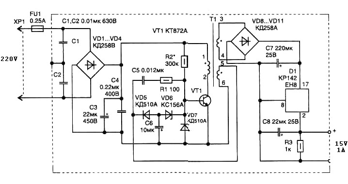
Overall, this 15 Watt switching power supply schematic represents a well-engineered solution for powering low to moderate power electronic devices while maintaining efficiency, compactness, and reliability.15 Watt switching power supply schematic diagram. Pulse transformer T1 is performed on the ferrite core M2500NMS-2 or M2000NM9 Sh5h5 size (cross-section of the magnetic coils at the location of 5G—5 mm with a gap in the center). Winding wire is made brand PEL-2. Winding 1. 2 turns of wire contains 600 0. 1 mm in diameter, 3-4 44 turns of 0. 25 mm diameter, 5-6 10 turns in the same wire as the primary winding. The schematic diagram come from circuit: Simple Switching Power Supply 15 Watt power supply. Go to that page to read the explanation about above power supply related circuit diagram. This Simple switching power supply for 15 Watt can be used to power any load up to 15. 20 watts and has smaller dimensions than a similar, but with the step-down transformer, operating at a frequency of 50 Hz. . This device allows up to 40, 000 volts by 220V AC. The AC to AC Converter circuit is powered from the mains through primary transformer (220-24) to isolate the network while reducing the input voltage.
Here can be used as a. The core of the Car DC to DC Converter 12V to ± 38 VDC is a pulse generator built on the TL494 chip. The circuit is designed to provide power supply to Monoblock Car Amplifier TDA7294. Generator frequency can be. The above scheme is a motorcycle battery charger, which is intended only for charging motorcycle batteries as its has a low charge current and thereby saving the battery plate from premature failure. This motorcycle battery charger circuit generate current of. The main part of any amplifier is the power supply. It is clear that to obtain a high output 12-volt battery is not enough. Therefore, we must first create a voltage converter, which enables a bipolar supply -60V with a. We aim to transmit more information by carrying articles. Please send us an E-mail to wanghuali@hqew. net within 15 days if we are involved in the problems of article content, copyright or other problems.
We will delete it soon. 🔗 External reference
Related Circuits
The 32-kHz low-power clock oscillator provides several advantages compared to traditional oscillator circuits that utilize a CMOS inverter. These inverter circuits often exhibit issues such as significant fluctuations in supply currents across a 3V to 6V supply range, making...
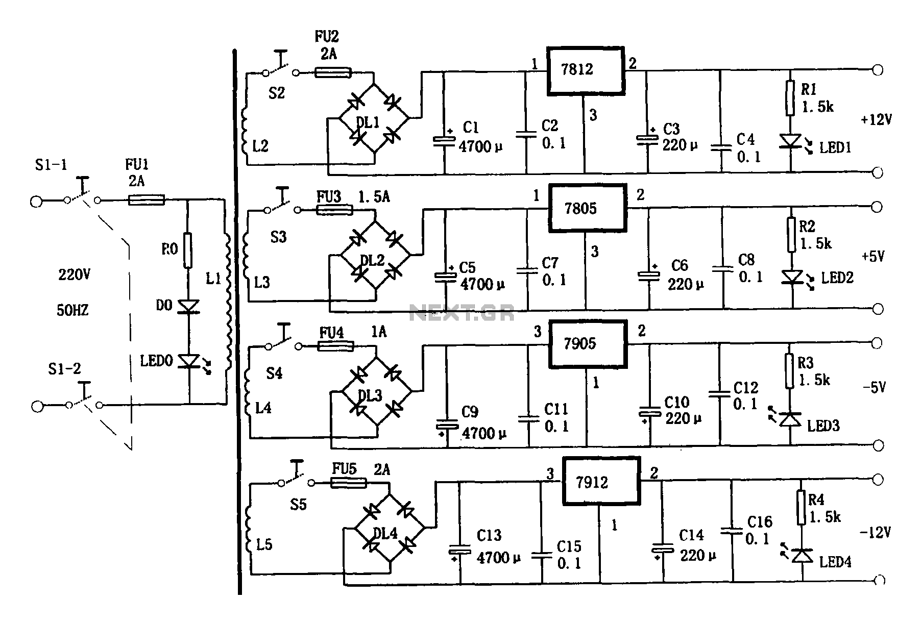
This document presents a multi-output power supply circuit. The circuit utilizes the secondary winding of a transformer and incorporates four voltage regulators: 7812, 7805, 7905, and 7912, providing independent output voltages of +12V, +5V, -5V, and -12V, respectively. Each...
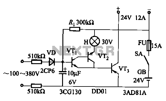
An AC-DC power supply without a power switching circuit is typically employed in lighting load circuits. When the power grid is restored, the standby power supply automatically switches on. The automatic switching circuit utilizes a transistor, as illustrated. The...
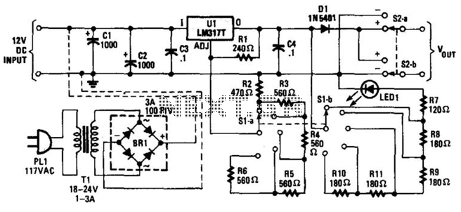
Intended as a replacement for poorly regulated "wall-type" AC/DC adapters, this circuit provides superior performance compared to simple, unregulated adapters. Available output voltages include 3, 6, 9, and 12 V. The DPDT switch functions as a polarity-reversal switch. Resistors...
The system utilizes a single circuit breaker instead of fuses. According to the schematic, switches provide 12 volts of power and ground to the window motors in opposite polarities, allowing the windows to move up and down. Troubleshooting should...
The losses in a bridge rectifier can become significant when low voltages are being rectified. The voltage drop across the bridge is approximately 1.5 V, which represents about 25% of an input voltage of 6V. The loss can be...
Warning: include(partials/cookie-banner.php): Failed to open stream: Permission denied in /var/www/html/nextgr/view-circuit.php on line 713
Warning: include(): Failed opening 'partials/cookie-banner.php' for inclusion (include_path='.:/usr/share/php') in /var/www/html/nextgr/view-circuit.php on line 713