
Power MOSFET Bridge Rectifier

In the design of a synchronous rectifier circuit, the choice of components and their arrangement is crucial for optimal performance. The use of MOSFETs instead of diodes allows for a significant decrease in voltage drop and associated power loss. The circuit is structured to ensure that the MOSFETs are activated in a coordinated manner, which is essential for maintaining efficiency during both halves of the AC cycle. The voltage dividers R1, R4, R5, and R8 play a critical role in determining the switching thresholds for the MOSFETs by providing feedback to the control IC (TL084). The careful selection of resistor values is necessary to ensure that the switching occurs at the optimal times, preventing losses associated with premature activation.
The internal diodes of the MOSFETs are particularly advantageous during the startup phase, allowing the circuit to begin operation even in the absence of a rectified voltage. This feature is vital for ensuring that the synchronous rectifier can start functioning as soon as AC power is applied. The design also considers the thermal management of the FETs, as they will experience varying currents that can lead to heating. Adequate heat dissipation methods, such as heat sinks, should be employed to maintain the reliability and longevity of the FETs.
When selecting FETs, it is important to consider not only their voltage and current ratings but also their on-resistance, as this directly impacts efficiency. The IRF4905 is a suitable alternative to the IRFZ48N, and its specifications should be matched to the requirements of the application. The adjustment of resistor values for different input voltages ensures that the circuit remains adaptable and maintains performance across a range of operating conditions. Overall, the synchronous rectifier circuit presents a modern solution to the inherent losses associated with traditional bridge rectifiers, making it an attractive choice for low-voltage applications.The losses in a bridge rectifier can easily become significant when low voltages are being rectified. The voltage drop across the bridge is a good 1. 5 V, which is a hefty 25% with an input voltage of 6V. The loss can be reduced by around 50% by using Schottky diodes, but it would naturally be even nicer to reduce it to practically zero.
That`s pos sible with a synchronous rectifier. What that means is using an active switching system instead of a passive` bridge rectifier. The principle is simple: whenever the instantaneous value of the input AC voltage is greater than the rectified output voltage, a MOSFET is switched on to allow current to flow from the input to the output. As we want to have a full-wave rectifier, we need four FETs instead of four diodes, just as in a bridge rectifier.
R1 R4 form a voltage divider for the rectified voltage, and R5 R8 do the same for the AC input voltage. As soon as the input voltage is a bit higher than the rectified voltage, IC1d switches on MOSFET T3. Just as in a normal bridge rectifier, the MOSFET diagonally opposite T3 must also be switched on at the same time.
That`s taken care of by IC1b. The polarity of the AC voltage is reversed during the next half-wave, so IC1c and IC1a switch on T4 and T1, respectively. As you can see, the voltage dividers are not fully symmetrical. The input voltage is reduced slightly to cause a slight delay in switching on the FETs. That is better than switching them on too soon, which would increase the losses. Be sure to use 1% resistors for the dividers, or (if you can get them) even 0. 1% resistors. The control circuit around the TL084 is powered from the rectified voltage, so an auxiliary supply is not necessary.
Naturally, that raises the question of how that can work. At the beginning, there won`t be any voltage, so the rectifier won`t work and there never will be any voltage. Fortunately, we have a bit of luck here. Due to their internal structures, all FETs have internal diodes, which are shown in dashed outline here for clarity.
They allow the circuit to start up (with losses). There`s not much that has to be said about the choice of FETs it`s not critical. You can use whatever you can put your hands on, but bear in mind that the loss depends on the internal resistance. Nowadays, a value of 20 to 50 mW is quite common. Such FETs can handle currents on the order of 50 A. That sounds like a lot, but an average current of 5 A can easily result in peak currents of 50 A in the FETs.
The IRFZ48N (55 V @ 64 A, 16 mW) specified by the author is no longer made, but you might still be able to buy it, or you can use a different type. For instance, the IRF4905 can handle 55 V @ 74 A and has an internal resistance of 20 mR. At voltages above 6 V, it is recommended to increase the value of the 8. 2-kR resistors, for example to 15 kR for 9V or 22 kR for 12 V. 🔗 External reference
Related Circuits
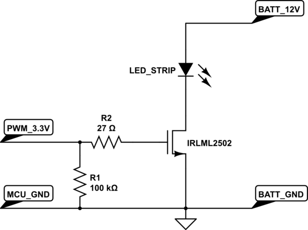
A strip of LEDs is controlled by a microcontroller using pulse-width modulation (PWM) to adjust brightness. The LED strip requires approximately 1.5A at 12V. The user, who has experience only with low-power digital electronics, seeks confirmation of their assumptions...

This design outlines a power supply circuit capable of producing a 5V source voltage. The circuit is constructed using TTL integrated circuits (ICs) and features a simple design. In circuits utilizing TTL ICs, the supply voltage is critical, as...
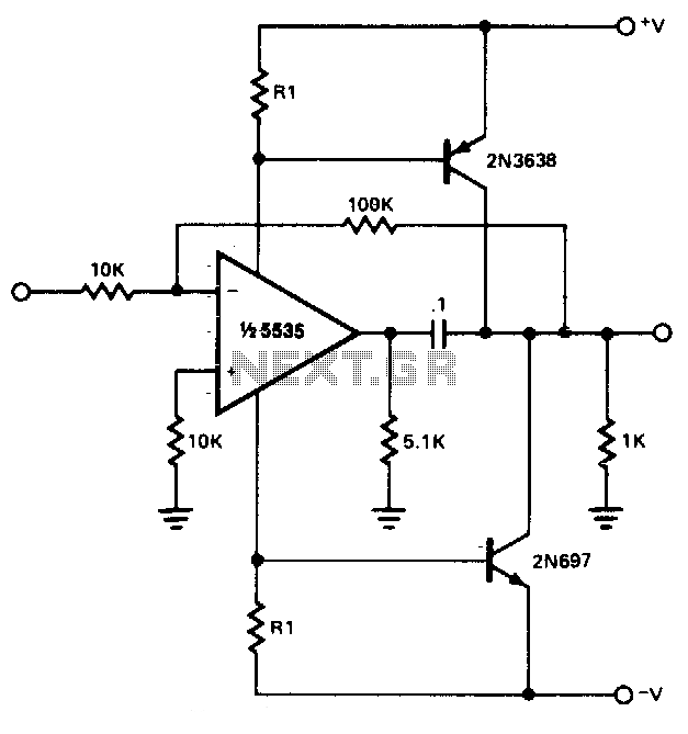
The power booster is designed to drive moderate loads. The circuit utilizes a NE5535 device. Other amplifiers may be substituted, provided that the resistor values (R1) are adjusted according to the Icc current requirements of the chosen amplifier. Additionally,...

The circuit utilizes a three-terminal adjustable integrated voltage regulator. It includes a gear set and a power supply voltage that is stepped down using a transformer rated at 17.5V x 2 AC. The output voltage after the bridge rectifier...
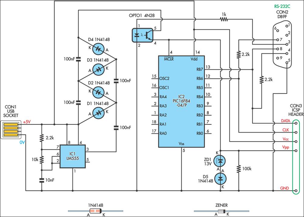
This simple circuit can be used to program the PIC16F84 and similar "flash memory" type parts. It utilizes a 555 timer IC to generate the programming voltage from a +5V rail, allowing the circuit to be powered from a...
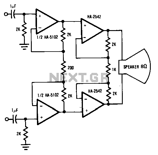
This circuit demonstrates a method to enhance the power capability of a drive system for audio speakers. Two HA-2542 amplifiers are utilized to operate on half cycles only, significantly increasing their power handling capacity. Bridging the speaker, as illustrated,...