
15v variable power supply circuit

This power supply circuit utilizes the robust 2N3055 power transistors, which are known for their high current capacity and thermal stability. The circuit is designed to provide a variable output voltage, adjustable from 1.5V to 15V, making it suitable for a variety of applications that require different voltage levels. The maximum output current of 500 mA ensures that it can power moderate loads effectively, while the stabilization feature maintains output voltage accuracy within a tolerance of 2% under specified load conditions.
The voltage adjustment is achieved through a potentiometer, allowing users to set the desired output voltage easily. The inclusion of an overload protection mechanism is critical for safeguarding both the power supply and connected devices. The T4 transistor plays a pivotal role in monitoring the output voltage. It continuously compares the voltage at the adjustable potentiometer (P1) with the output voltage. When the output voltage exceeds the regulated level by 0.65V, T2 is triggered, which in turn controls the Darlington pair formed by T3 and T5, effectively reducing the output current to prevent damage due to overload.
The reference voltage for the T4 transistor is supplied by a 15V zener diode, ensuring a stable reference point for the voltage comparison. This design feature enhances the reliability of the overload protection circuit, ensuring that the power supply operates safely across its entire range of output voltages. Overall, this 15V variable power supply circuit is an effective solution for applications requiring adjustable voltage and robust current handling capabilities.This 15v variable power supply electronic project is designed using 2N3055 transistors. Output voltage of this variable power supply can be adjusted in the range between 1. 5 and 15 volts. This 2N3055 15v variable power supply can provide a maximum current of 500 mA. Stabilization is better than 2%, if the currents do not exceed 350 mA. Voltage is set using a potentiometer, and the presence of overload is announced by an audible indication of overload. T4 transistor compare the voltage at the cursor P1 with the output. When this voltage is higher with 0. 65 V than regulated voltage, T2 opens, leading to suppression of the current Darlington power stage, T3-T5.
In this mode, the output voltage of the source is higher than 0. 65 V reference voltage on the base of T4, which comes from a 15 V zener diode. 🔗 External reference
Related Circuits
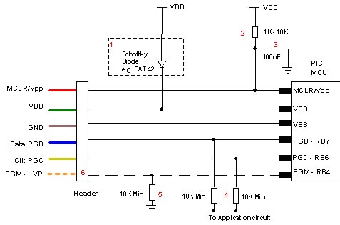
Microchip does not recommend any specific circuit for In-Circuit Serial Programming (ICSP). Various diagrams exist for different tools, such as Pro Mate and PICKit2, which feature similar circuitry with minor variations. Some schematics may suggest resistor values that are...
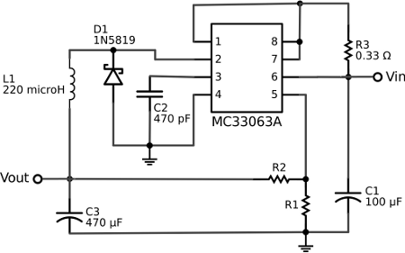
The voltage regulator integrated into the Arduino Uno is a linear-type regulator, which exhibits poor efficiency. When operating the ATmega238 at 5V with a 9V battery, nearly half of the battery's energy is wasted as heat by the regulator....
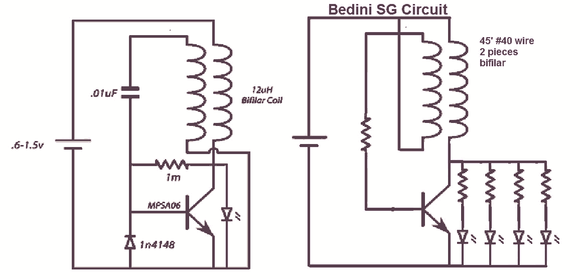
It would be beneficial to obtain schematics of the Joule Thief and Bedini oscillator circuit connections. This is an area that has not been previously explored. The schematic on the left was sourced from the Energetic Forum, while the...
%2Bwith%2Banimation%2Bsimulation%2Bcircuit.png)
The Johnson digital counter, also known as the Twisted Ring Counter, is a synchronous shift register that incorporates feedback from the inverted output (Q`) of the last flip-flop. The Q` output of the final flip-flop is connected back to...
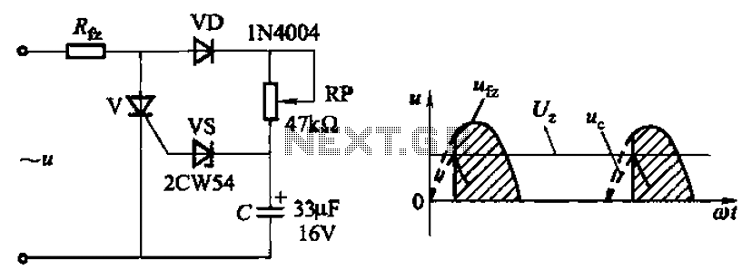
Circuit characteristics: A simple phase shift range of 180 degrees; exhibits good linearity and control accuracy compared to the first two options, making it suitable for low voltage applications, particularly in less demanding electroplating and electrolysis power supplies. The described...
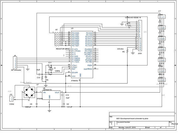
DTMF-based Robo Car design using the 8051 microcontroller project. This project demonstrates a method to control a domestic system using the DTMF tone generated by a telephone instrument when the user presses the keypad buttons of a mobile phone...