
An Efficient Low-Power Arduino Switching Voltage Regulator
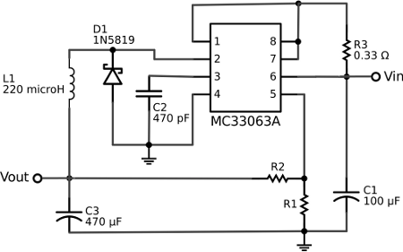
The Texas Instruments MC33063A is a versatile DC/DC converter capable of performing various voltage regulation tasks. When configured as a buck regulator, it efficiently steps down the voltage from a higher level, which is essential for powering low-voltage devices like microcontrollers and wireless modules. The circuit typically includes external components such as inductors, diodes, and capacitors, which are crucial for smoothing the output voltage and ensuring stable operation.
In this design, the selection of resistor values R1 and R2 is critical for determining the output voltage. The formula used to calculate the output voltage (Vout) in a buck configuration is given by:
\[ V_{out} = V_{ref} \times \left(1 + \frac{R2}{R1}\right) \]
where \( V_{ref} \) is the reference voltage of the MC33063A, typically around 1.25V. By choosing R1 = 100 kOhm and R2 = 200 kOhm, the output voltage is adjusted to approximately 3.75V, which is suitable for the ATmega328 microcontroller and the XBee radio module, ensuring reliable operation.
The efficiency of this switching regulator is markedly higher than that of linear regulators, as it minimizes power loss by converting excess voltage into usable current rather than dissipating it as heat. This results in lower current consumption, particularly when the load is minimal, thereby prolonging battery life significantly.
In summary, the implementation of the MC33063A as a buck regulator not only enhances the efficiency of the power supply for the Arduino and associated components but also extends the operational lifespan of the battery, making it an ideal choice for portable, battery-operated projects.The voltage regulator built onto the Arduino Uno is a linear-type regulator and is horribly inefficient. If you are running the ATmega238 at 5V using a 9 V battery, approximately half of the battery`s energy will be dissipated as heat by the regulator.
This post demonstrates a DC/DC switching-type voltage regulator circuit that can be use with a b readboard Arduino and is much more efficient then a typical 7805 regulator. The switching regulator used is a Texas Instruments MC33063A. This IC can be used with external components to make a boost regulator (to step up voltage), a buck regulator (to step down voltage), or an inverting regulator. Here I am setting it up as a buck regulator to step down a 12 V battery pack to run a 3. 3 V breadboard Arduino and XBee radio. Here is the voltage regulator circuit schematic. In my design, I am using R1 = 100 kOhm and R2 = 200 kOhm giving me an output voltage of approximately 3.
75 V to power both an ATMega328 and an XBee Series 1 radio. Depending on the values of R1 and R2, this switching regulator circuit uses about 2. 5 to 3. 5 mA of current when not powering a load. This compares to about 10 15 mA for a 7895 linear regulator. By using this regulator circuit design, my battery lasts for almost two weeks. 🔗 External reference
Related Circuits
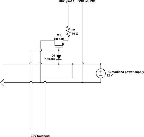
A 9 V DC battery initially powered the solenoid valve effectively. However, the solenoid did not generate sufficient force due to inadequate DC power. A modification was made to use a computer power supply as the power source. Providing...
In the typical dynamo charging circuit, B+ and B- are the battery connections. D+ and D- go to the dynamo brushes, while DF is the field connection, with its other end returned to D+ inside the dynamo. Please note...
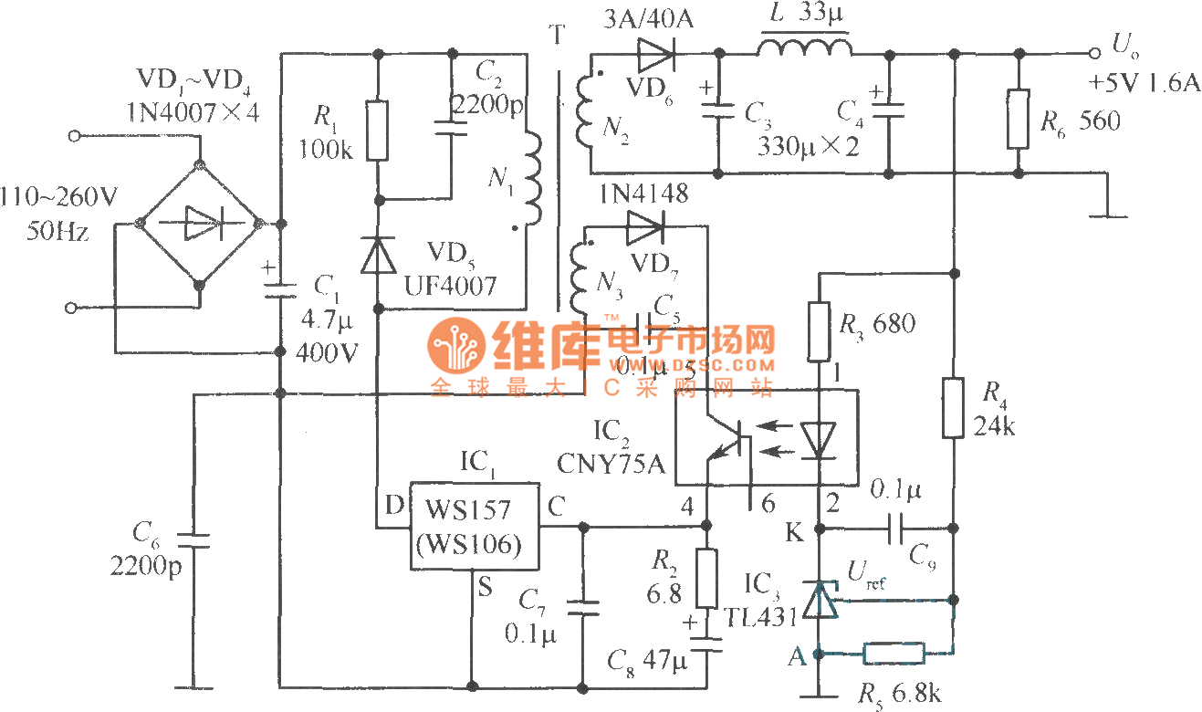
The +5V, 1.6A precision switching power supply circuit is depicted in the figure. This circuit utilizes a photoelectric coupler (CNY75A) and an adjustable precision parallel regulator (TIA31). R3 serves as the current limiting resistor, while R4 and R5 function...
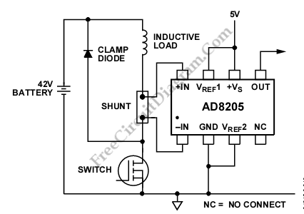
The AD8205 can be utilized to create a high-side current sensing circuit with a low-side switch. In this configuration, an inductive load (such as a solenoid) and a resistive shunt are incorporated. The resistive shunt is positioned on the...
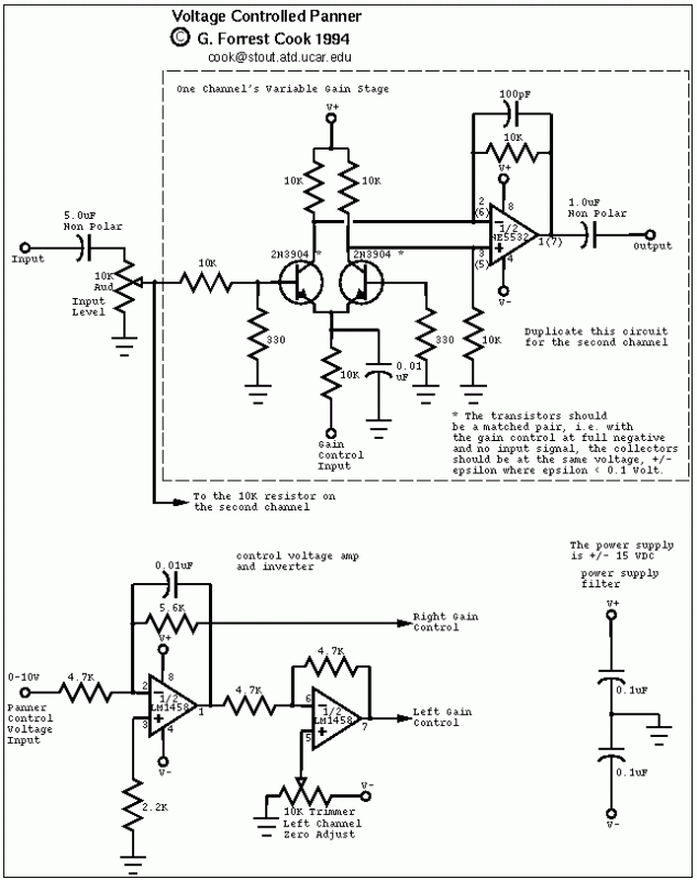
The control voltage is fed into the first half of a 1458 op-amp, this stage inverts the signal and sets the offset and gain for the right channel gain control circuit. This signal is then fed into the second...
The purpose of this application note is to present an example circuit illustrating the operation of the XR-T5683 device at a data rate of 10.1 Mbps. This note includes the results of measurements taken on the XR-T5683 at this...
Warning: include(partials/cookie-banner.php): Failed to open stream: Permission denied in /var/www/html/nextgr/view-circuit.php on line 713
Warning: include(): Failed opening 'partials/cookie-banner.php' for inclusion (include_path='.:/usr/share/php') in /var/www/html/nextgr/view-circuit.php on line 713