
1B32 bridge sensor signal conditioner with multi-channel application circuit when the pressure sensor
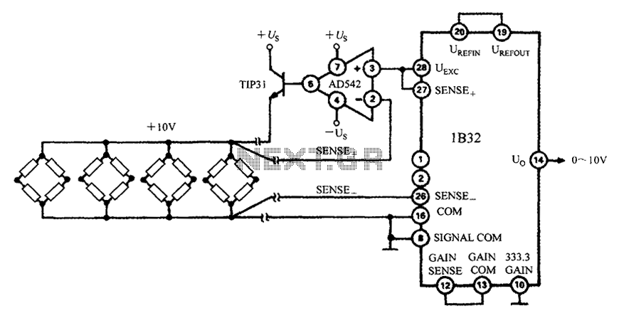
The 1B32 application circuit is designed to interface multiple pressure sensors, utilizing an excitation power source to ensure accurate sensor readings. The AD542 Bi-FET serves as the initial stage of the circuit, providing a stable and buffered output that is crucial for maintaining signal integrity when driving multiple bridge sensors. This configuration allows for the effective amplification of the signals produced by the pressure sensors, which are typically low-level outputs.
The TIP32 transistor is employed to manage the current required by the bridge sensors, ensuring that they receive adequate power for optimal performance. The TIP31 NPN transistor is selected for its robust specifications, including a maximum reverse voltage of 45V, which ensures that the circuit can handle varying input conditions without damage. Its capability to support a collector current of 3A and a power consumption of 40W makes it suitable for applications that require significant power handling.
Operating within a temperature range of -25 to +80 degrees Celsius, the circuit is designed for reliability in diverse environmental conditions. The +10V, 300mA excitation source provided by the circuit is essential for powering the sensors, ensuring they function correctly and produce accurate readings. The gain of 333.3 is a critical parameter, allowing for the amplification of sensor signals to a usable level, facilitating further processing or monitoring applications. This configuration is particularly useful in industrial applications where precise pressure measurements are necessary for system control and monitoring.1B32 application circuit with multiple pressure sensor shown in Fig. Excitation power through AD542, after TIP32 then drive multiple bridge sensors. AD542 is a Bi-FET as the in put stage of the operational amplifier, where the act as a buffer. TIP31 NPN epitaxial type power transistors, the maximum reverse voltage of 45V, maximum collector current of 3A, the maximum power consumption of 40W. The circuit in the temperature range of -25 ~ + 80 to provide + 10V, 300mA source of excitation. The 1B32 of 333.3 GAIN grounded, the gain is set as 333.3 times.
Related Circuits
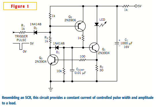
A typical silicon-controlled rectifier (SCR) requires a trigger current to latch on. Once the device is latched, the current flowing through the SCR is determined only by the external component values. The SCR lacks the ability to limit current...
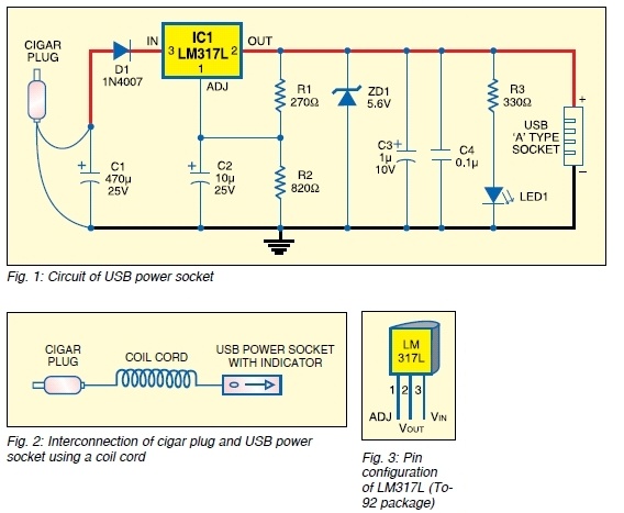
The safe 12V car adapter described here can be used to limit the current from a +12 volt car battery, available from the in-dash cigar lighter power port, to below 2.6A. The 12V car adapter is designed to ensure that...
The following circuit illustrates the connection of the Devantech SRF04 Ultrasonic Sensor to the SV203 powered PPRK Circuit Diagram. This circuit is based on the Devantech SRF04 sensor and features a minimum initiation time of 10 milliseconds for the...
A functional circuit utilizing an operational amplifier (op-amp); however, the instructor indicated that op-amps can be challenging to work with and provided transistors as an alternative. Operational amplifiers (op-amps) are versatile components commonly used in various electronic circuits for...
A unit that is often very useful for isolating two stages in sound circuits. This circuit incorporates an amplification unit with a gain of X1. It employs only local negative feedback rather than total negative feedback, resulting in very...
The idea to produce a standard TV PAL signal using a SVGA graphics card was born a few years ago, where cheap graphics cards with TV output were still not available. To achieve a CCIR conform TV signal with...
Warning: include(partials/cookie-banner.php): Failed to open stream: Permission denied in /var/www/html/nextgr/view-circuit.php on line 713
Warning: include(): Failed opening 'partials/cookie-banner.php' for inclusion (include_path='.:/usr/share/php') in /var/www/html/nextgr/view-circuit.php on line 713