
1Khz Square-Wave Generator
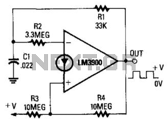
This circuit operates as a basic astable multivibrator, utilizing operational amplifiers for generating square wave signals. The configuration involves two resistors, R3 and R4, which are connected in parallel when the output state is high. Capacitor C1 is charged through resistor R1, which sets the time constant for the charging process. As the voltage across C1 reaches 2/3 of the supply voltage, the op-amp switches from a high to a low output state due to the regenerative feedback mechanism inherent in the circuit design.
Once the output transitions low, C1 begins to discharge through R1. During this discharge phase, R4 becomes inactive, and the discharge current is solely governed by R3. The discharge continues until the voltage across C1 drops to approximately 1/3 of the supply voltage, at which point the op-amp transitions back to a high output state, completing one cycle of the square wave.
The frequency of the output square wave is primarily determined by the values of R1, R3, and C1, as well as the supply voltage. The design is particularly suitable for applications requiring low-frequency square wave generation, typically in the range of a few kilohertz. However, the LM3900's limited slew rate of 0.5 V/μs results in slower rise and fall times for the output waveforms, which may restrict its use in high-speed applications. Overall, this circuit provides a straightforward method for generating symmetrical square waves, making it a valuable component in various electronic applications. When the output is high, R3 and R4 are in parallel, and CI charges via Rl until the current in R2 equals that a t the noninverting terminal. This action occurs when CI"s voltage rises to 2/3 of the supply voltage. At that point, the circuit switches regerier-atively. The output switches low and CI starts to discharge via Rl. Now, R4 is effectively disabled and the current to the noninverting terminal is determined solely by R3, so CI discharges until the current through R2 falls slightly below that of R3. This happens when the voltage across CI falls to about 1/3 of the supply voltage. At that point, the circuit again switches regeneratively, and the output again goes high. This circuit is useful for generating symmetrical square waves with maximum frequencies of only a few kHz.
Because of the poor slew-rate characteristics of the LM3900 (0.5 V7/is), the output waveforms have rather slow rise and fall times. 🔗 External reference
Related Circuits
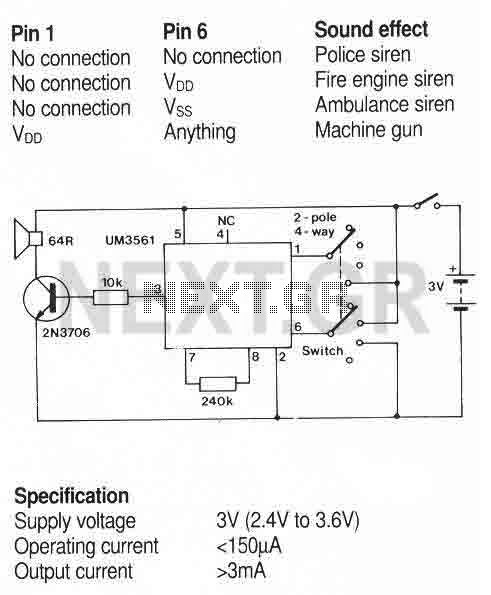
A simple sound generator IC that can produce four sound effects. Designed for use in toys, the effects are selected by varying the connections to pins 1 and 6 as follows. More: A usual toy sounder IC circuit. The sound...
This project demonstrates the construction of a robot voice generator utilizing the HT8950 integrated circuit, which is a robust voice modulation IC. The circuit features a robot function, a vibrato function, and additional capabilities. The robot voice generator circuit employs...
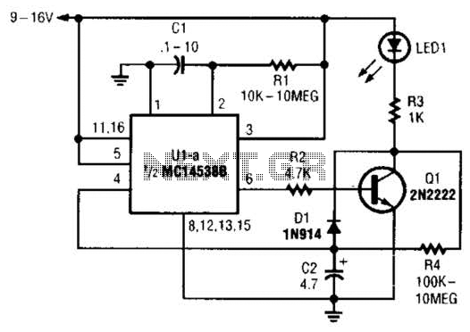
When power is first applied to the circuit, capacitor C2 begins to charge through LED1, resistor R3, and resistor R4. When the voltage across C2 reaches the input trigger level of operational amplifier U1, the output at pin 6...
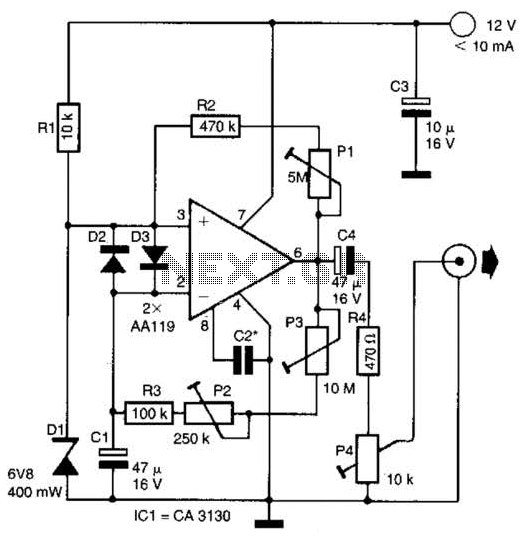
This circuit generates noise pulses suitable for test purposes. A Zener diode serves as the noise source. IC1 functions as a relaxation oscillator. P1 determines the noise bandwidth, while P2 and P3 control the noise amplification. The current consumption...
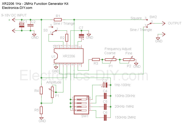
The Function Generator is essential laboratory equipment. The module described here is based on the high-quality XR2206 integrated circuit (IC). The 1Hz - 2MHz XR2206 Function Generator is capable of producing high-quality sine, square, and triangle waveforms with high...
This circuit utilizes the versatile MAX038 function generator. While some advanced features of this integrated circuit (IC) are disabled in this configuration, it is capable of generating sine, triangle, and square waves by adjusting the A0 and A1 pins,...