
1W UHF Linear Amplifier with BLW33
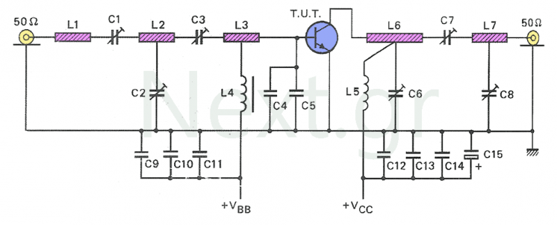
The theoretical circuit requires a stabilized power supply that provides a voltage of 25 V and a current capacity of at least 0.5 A. The optimal operating point for Class A transistors is a 24 V power supply with a collector current of 33 Ohms, allowing for a minimum output of 1.2 W. The BLW33 transistor is housed in a ceramic SO122 package, and care must be taken not to damage it, as its base is made of beryllium oxide (BeO), which is highly toxic and carcinogenic. The circuit includes three fixed surface mount capacitors (C1, C4, and C8), where C1 isolates the constant voltage from the drive circuit, while C4 and C8 are used for decoupling. The adjustment of the transistor to the 50 Ohm output line is facilitated by variable capacitors C10 and C11, and the input of the amplifier is adapted using variable capacitor C2.
The circuit design favors transmission lines over coils for ease of construction and stable performance. To operate in Class A, the transistor requires an additional biasing circuit for its base. This circuit consists of a BD136 transistor (T2) and a voltage divider formed by resistors R1, R7, and R8, which polarizes the base of T2. Resistor R6 regulates the base current of the BLW33 transistor.
The components used in this circuit include various resistors and capacitors, as well as the transistors and other elements necessary for its operation. The resistors include R1, R3, R5 at 10 Ohms; R2 at 33 Ohms; R4 at 220 Ohms; R6 as a 220 Ohm trimmer; R7 at 150 Ohms; and R8 at 1.8 kOhms. The capacitors consist of C1, C4, and C8 at 100 pF; C2, C10, and C11 at 1-4 pF; C3 at 100 nF; C5 at 470 nF; and C6, C7 at 6.8 pF/63V. The circuit's active components include T1 (BLW33), T2 (BD136), D1 (BAW62), and an inductor L1 valued at 1 μH.
Construction of the amplifier involves assembling the components onto a double-sided PCB, with the BLW33 transistor requiring a small heatsink for thermal management. The polarization circuit is typically placed outside the amplifier circuit to prevent interference.
This amplifier circuit is designed for efficient operation within the specified frequency range while ensuring stability and performance through careful component selection and layout design.This circuit is an amplifier for small transmitters operating in the UHF band, specifically in the 450-800MHz range. The amplifier works in class A and we used the well-known Philips BLW33 transistor for its manufacture.
The construction, although simple, can be said to be quite critical due to the high frequency singularity. To achieve this, a double-sided printed circuit is required, where the lower face is used for grounding with conventional materials.
Is preferred not to use many surface support materials so you can make the amplifier as easily as possible. The amplification of the BLW33 transistor is 8.5dB at 860 MHz and 11.5dB at 470MHz.
So if we give it as a driving power of -60dB, then its output will deliver a power of 120mW at 470MHz and 900mW at 860MHz.
Increasing the output power as a function of the input power does not mean that it will deliver at the same time a clear signal. The output signal from one point on will be distorted. This problem arises because of intermodulation derivatives.

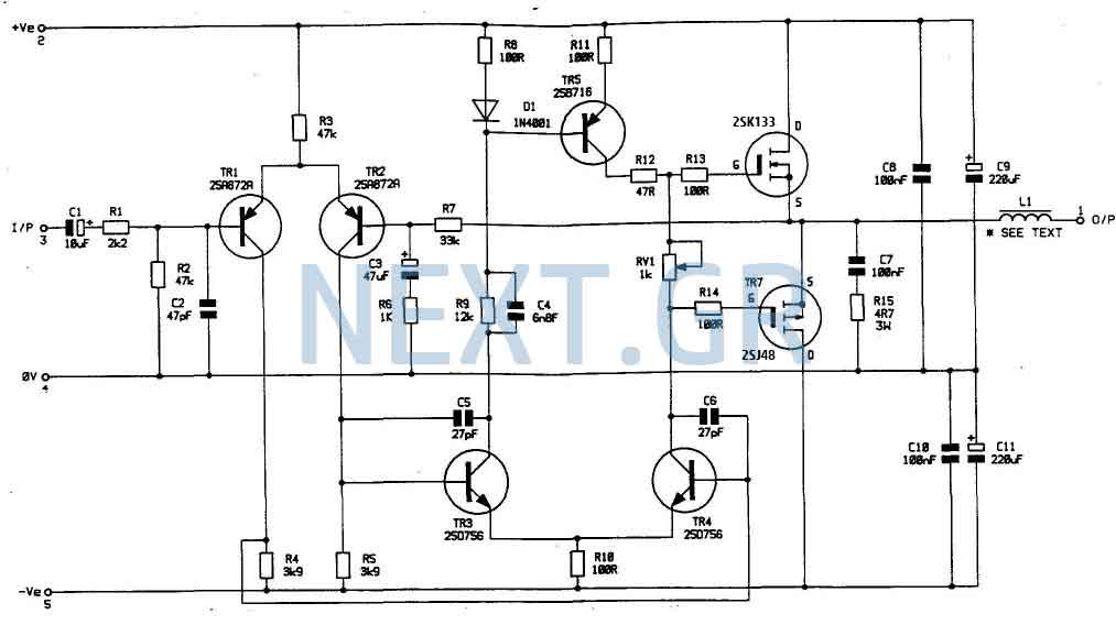
The theoretical circuit
The transistor to work needs, like any construction, a stabilized power supply with very good stabilization, output voltage 25V and current capacity of at least 0.5A.
The most efficient point of class A transistors is the 24V power supply and the 33 Ohm collector current.
Under these operating conditions it can pull out at least 1.2W. The transistor is available in ceramic shell SO122. If for any reason the transistor suffers some damage, you do not have to mistreat it, as Of course any other. Its base is made up of beryllium oxide (BeO), a substance that is extremely toxic and carcinogenic. The theoretical circuit is shown in the figure.
As we can see, there are three fixed surface mount capacitors C1, C4 and C8.
C1 is to isolate the constant voltage that can be displayed by the drive circuit while the others are used for decoupling.
The adjustment of the transistor to the 50Ω output line is done with the help of the C10 and C11 variable capacitors, and the power lines at the output circuit respectively. Similarly, the input of the amplifier is adapted via the variable capacitor C2.

In the circuit is preferred the transfer lines instead of coils to make construction easier.
The transmission lines have a more stable behavior than the coils. The transistor, in order to work in class A, needs an additional polarization circuit for its base.
This circuit consists of a transistor, T2 (BD136) and a voltage divider with the resistors R1, R7 and R8 polarizing the base of T2 and the triplet R6, which regulates the base current of the BLW33. The polarization circuit is shown in the figure above.
Components
| Resistors | Capacitors | Other |
|
R1,R3,R5 = 10Ω R2 = 33Ω R4 = 220Ω R6 = 220Ω trimmer R7 = 150Ω R8 = 1,8ΚΩ |
C1,C4,C8 = 100pF C2,C10,C11 = 1-4pF C3 = 100nF C5 = 470nF C6,C7 = 6,8pF/63V |
T1 = BLW33 T2 = BD136 D1 = BAW62 L1 = 1μH |

Construction
The first image shows the theoretical circuit of the circuit and the printed double-sided PCB, in which you will place the components.
The BLW33 transistor needs a small heatsink to cool. Coil H has a value of 1μH. For the polarization circuit, there is not PCB, since it is customary to be placed outside the amplifier circuit for protection purposes and to avoid any interference it may cause to the circuit.
Related Circuits
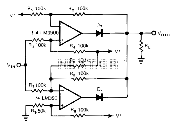
The non-inverting amplifier has a gain of R2/R3 (1 in this case) and produces a voltage of V during a positive excursion of Vin with respect to ground. The inverting amplifier accommodates the negative excursions of V; its gain...
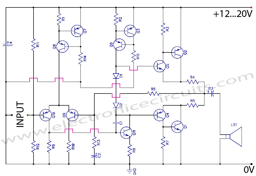
Discrete Class AB Transistor Audio Power Amplifier Circuit Diagram. This is a Class AB transistor power amplifier. It is a simple amplifier. The discrete Class AB transistor audio power amplifier is designed to provide efficient amplification of audio signals while...
The objective of Linkwitz's article was to reduce distorted spatial reproduction when listening to recorded stereo music with headphones, addressing the "super stereo" effect where the music appears to originate from within one's head. To eliminate this spatial distortion,...
Most devices used in amplifier output stages exhibit significant non-linearity, with transistors (both bipolar and FET) being particularly problematic. These components are almost always employed within a global feedback loop to mitigate their non-linear characteristics. Similarly, tetrode and pentode...
After restoring a Fisher 400, the search for another tube amplifier began, motivated by a desire to apply newly acquired skills. Importing equipment from the USA to the European Union proved costly, with shipping fees around $200 to $250,...
In my opinion that is the best buildable high power amplifier out there. Quality of sound is just remarkable. This is a real bomb proof amplifier like the best Valve amps. Power supply circuit is also shown. Now lets...
Warning: include(partials/cookie-banner.php): Failed to open stream: Permission denied in /var/www/html/nextgr/view-circuit.php on line 713
Warning: include(): Failed opening 'partials/cookie-banner.php' for inclusion (include_path='.:/usr/share/php') in /var/www/html/nextgr/view-circuit.php on line 713