
2 Transistor FM Voice Transmitter

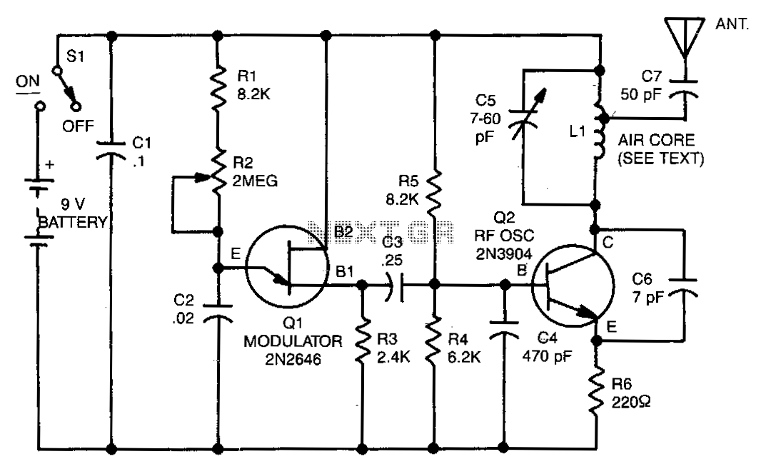
This low-power RF transmitter circuit is suitable for short-range applications, particularly in the FM broadcast band. The choice of BC548 transistors allows for a compact and efficient design, even though they are not specifically optimized for RF applications. The ECM microphone insert provides good audio fidelity, and the option to use a dynamic microphone broadens its usability.
The coil L1 is critical for tuning the transmitter; its 7 turns create an inductor that, along with the tuning slug, allows for precise frequency adjustments. This tuning capability is essential for ensuring compliance with local regulations regarding frequency use and minimizing interference with other broadcasts.
The antenna design is equally important; a short wire antenna is preferred to avoid damping effects that longer wires may introduce. This circuit's performance can be influenced by the surrounding environment, so careful placement and orientation of the antenna may enhance transmission range.
While constructing the circuit on a PCB is recommended for optimal performance, using veroboard is a viable alternative, especially for prototyping. Care should be taken to minimize lead lengths to reduce parasitic capacitance and inductance, which can affect circuit performance. Additionally, breaking tracks at strategic points can help isolate different sections of the circuit, improving overall functionality.
The warning against holding the circuit while speaking highlights the importance of understanding the effects of body capacitance on RF circuits. This insight is crucial for users to achieve the best performance from the transmitter, ensuring that it operates effectively without unwanted damping of oscillations.Although only low power this circuit may be tuned to operate over the range 87-108MHz with a range of 20 or 30 metres. I have used a pair of BC548 transistors in this circuit. Although not strictly RF transistors, they still give good results. I have used an ECM Mic insert from Maplin Electronics, order code FS43W. It is a two terminal ECM, but ordinary dynamic mic inserts can also be used, simply omit the front 10k resistor. The coil L1 was again from Maplin, part no. UF68Y and consists of 7 turns on a quarter inch plastic former with a tuning slug. The tuning slug is adjusted to tune the transmitter. Actual range on my prototype tuned from 70MHz to around 120MHz. The aerial is a few inches of wire. Lengths of wire greater than 2 feet may damp oscillations and not allow the circuit to work. Although RF circuits are best constructed on a PCB, you can get away with veroboard, keep all leads short, and break tracks at appropriate points. One final point, don`t hold the circuit in your hand and try to speak. Body capacitance is equivalent to a 200pF capacitor shunted to earth, damping all oscillations. I have had some first hand experience of this problem. 🔗 External reference
Related Circuits
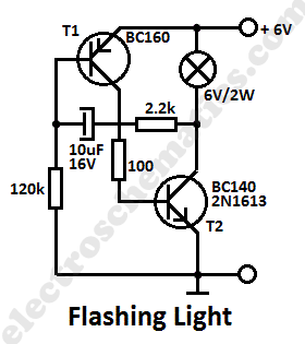
This simple flashing light circuit operates at 6 volts and 0.5A, exhibiting low current consumption when the light bulb is turned off. The frequency of the flashing is predetermined. The circuit consists of a power supply, typically a battery or...

This FM transmitter circuit is compact, similar to a previous single-chip FM transmitter, but it is monophonic in nature. The circuit can be observed in the provided schematic. This monophonic FM transmitter is designed to operate on a single frequency,...

Most consumer electronic devices utilize infrared remote controls for convenient operation. The carrier frequency of these remote controls typically ranges from 36 kHz to 38 kHz. Control codes are transmitted to the device's receiver in a serial format, which...

A 175 MHz high-frequency amplifier circuit utilizing a field-effect transistor (FET) is presented. The field-effect transistor used is the 3D04H, along with its associated components and parameters. The 175 MHz high-frequency amplifier circuit is designed to amplify signals in the...
The range of this transmitter is approximately 50 feet with a short whip antenna. The tone generator consists of a unijunction transistor (Q1) along with resistors R1, R2, R3, and capacitor C2. Transistor Q1 operates by pulsing on and...

This FM transmitter circuit is very simple and has acceptable transmission. The signal transmitted from this FM transmitter circuit can be received at almost 300 meters in open air. The circuit requires a 3-volt operating voltage and can be...