
300m FM transmitter circuit design project

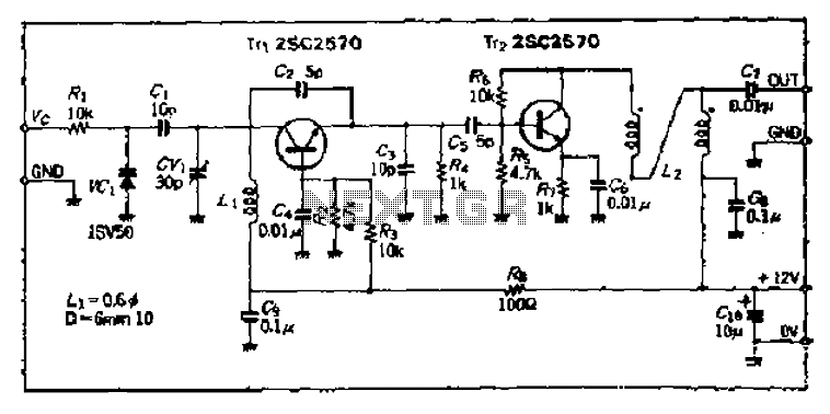
This FM transmitter circuit operates effectively within the FM broadcast band, providing a range of approximately 300 meters in open environments. The circuit requires a 3-volt power supply, making it suitable for battery-operated applications. The tuning mechanism is flexible; the circuit can be adjusted across the entire FM band, which typically ranges from 88 MHz to 108 MHz.
The heart of the transmitter is a coil, which must be carefully constructed and adjusted. Once the coil is soldered, it is crucial to ensure that the coils are separated by about 0.5 to 1 mm to avoid short-circuiting, which could hinder performance. For frequency modulation, the circuit can utilize either a trim capacitor or a fixed capacitor. While a fixed capacitor can be used, it limits the tunability of the circuit. Adjusting the spacing between the coils or introducing a ferrite core can provide some frequency variation, but utilizing a variable capacitor is the preferred method for achieving precise tuning.
To maximize transmission efficiency, an antenna must be connected to the aerial point of the circuit. The length of the antenna is critical; for an FM frequency of 100 MHz, a half-wavelength antenna should measure approximately 150 cm, while a quarter-wavelength antenna should be about 75 cm. Proper antenna design is essential for optimal signal transmission and reception, ensuring that the circuit can effectively broadcast signals over the intended range.
In summary, this simple FM transmitter circuit offers a practical solution for low-power broadcasting, with careful attention to component selection and circuit assembly leading to successful operation in various applications.This fm transmitter circuit is very simple and it has a acceptable transmission. The signal transited from this fm transmitter circuit can be received at almost 300 meters in open air. The circuit require a 3volts operating voltage and can be tuned anywhere in the FM band. After the coil in soldered into place spread the coils apart about 0. 5 to 1mm so that they are not touching. If you don`t have a trim cap you can use a fixed value capacitor and you can vary the TX frequency by adjusting the spacing of the coils or placing a small piece of ferrite inside the coil, but the better way to change the transmission frequency is to use a variable capacitor. Connect a half or quarter wavelength antenna (length of wire) to the aerial point. At an FM frequency of 100 MHz these lengths are 150 cm and 75 cm respectively. 🔗 External reference
Related Circuits
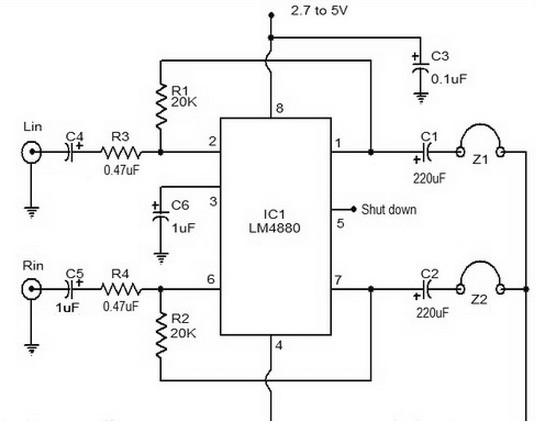
The LM4880 is a dual audio HiFi amplifier integrated circuit from National Semiconductor. This headphone amplifier circuit is specifically designed to produce high-quality audio output with a minimal number of components. The LM4880 integrated circuit is capable of delivering...

This circuit design for a low current relay is intended for use in battery-operated electronic devices, with an operating current in microamperes (µA). It utilizes a bistable relay and additional components to enable the relay to function similarly to...
The following circuit illustrates a LEGO Light Sensor Circuit Diagram. This circuit is based on the LM358 integrated circuit, which features a dual operational amplifier and high-speed capabilities. The LEGO Light Sensor Circuit utilizes the LM358, a versatile dual op-amp...

The micro ampere meter presented here functions as a DC millivolt meter. It achieves full-scale deflection with a 0.1V input. The current to be measured flows through a known resistance R, and the voltage drop across this resistance is...
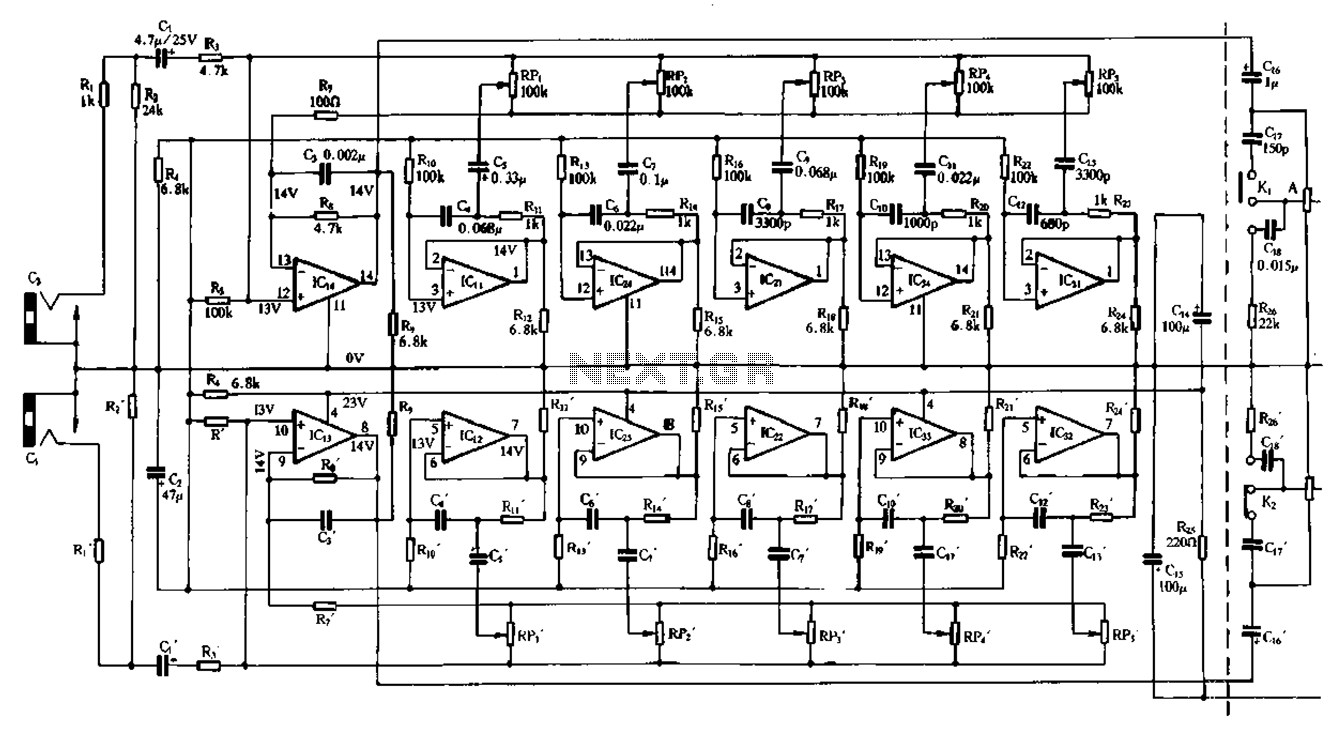
Figure 1-98 illustrates a double five-band equalizer circuit featuring a secondary connection. In this configuration, IC1 and IC14 serve as voltage amplifiers for each channel of the equalizer. The circuit also includes IC11, IC24, IC2, IC34, IC31, IC12, IC23,...
The Bong circuit is a high-frequency Colpitts oscillator that utilizes a Ge coil (L). It features two heads and is designed for simple production. The frequency of oscillation can be determined, and testing is conducted to ascertain the value...