
20 kHz ASTABLE
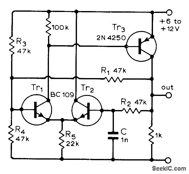
This single-capacitor circuit design is characterized by its robustness, making it suitable for applications requiring stable performance under varying environmental conditions. The circuit primarily utilizes a single capacitor, which simplifies the design while ensuring reliable operation across different temperatures and supply voltages.
The frequency stability of 0.05% across a voltage range of 6V to 12V indicates that the circuit is well-suited for applications where power supply variations are common. This feature is particularly beneficial in battery-operated devices where voltage levels may fluctuate as the battery discharges.
Timing in the circuit can be adjusted by varying the values of resistors R1 and R2, along with the capacitance of C. This flexibility allows for customization of the timing characteristics to meet specific application requirements. By selecting appropriate resistor and capacitor values, the designer can achieve the desired timing intervals, making this circuit versatile for different timing applications.
The duty cycle, which is defined as the ratio of the on-time to the total cycle time, is influenced by the resistors R3 and R4. A 50% duty cycle indicates that the output signal is high for half of the cycle duration, which is often desirable in applications such as pulse-width modulation (PWM) or clock signal generation. The ability to maintain this duty cycle with the specified resistor ratios enhances the circuit's functionality in various electronic applications.
Overall, this single-capacitor circuit design is an efficient solution for timing and frequency generation, providing reliable performance and ease of customization for a wide range of electronic applications.Single-capacitor circuit is reIiable over wide range of temperatures. voltages. and transistor gains. Frequency varies only by 0. 05% for supply voltage changes between 6 and 12 V. Timing can be changed with R1. R2. and C. Ducy cycle depends on ratio of R3. to R4. and is 50% forvaluesshown. -C. Horwitz, Tolerant Astable Circuits. Wireless World. Feb . 1975, p93. 🔗 External reference
Related Circuits
This is a very simple circuit utilizing a 555 timer IC to generate a square wave of frequency that can be adjusted by a potentiometer. With values given, the frequency can be adjusted from a few Hz to several...
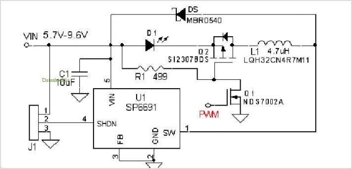
Loop stability analysis typically begins with an open-loop Bode plot of the system being examined, such as the power stage of a buck or flyback converter. This plot allows the designer to extract phase and gain information within the...
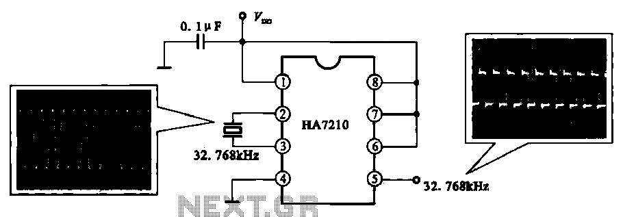
This circuit illustrates a 32.768 kHz micro-power clock oscillator, suitable for use in mobile phones, laptop computers, and home appliances. It generates a clock signal that can be utilized in various applications. The 32.768 kHz micro-power clock oscillator circuit is...
Multivibrators are two-state devices that are extensively used in digital electronics. Bistable multivibrators, also known as flip-flops, serve as fundamental memory elements. Multivibrators can be categorized into three primary types: astable, monostable, and bistable. Each type has distinct operational characteristics...
Frequency modulation (FM) can be used to transmit an analog voltage level signal with good noise immunity. The transmission itself might employ different techniques. Frequency modulation (FM) is a method widely utilized in communication systems to encode information in a...
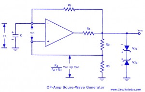
Non-sinusoidal waveform generators are also referred to as relaxation oscillators. The op-amp relaxation oscillator described is a square wave generator. Generally, square waves are relatively simple to produce. Similar to the UJT relaxation oscillator, the frequency of oscillation in...
Warning: include(partials/cookie-banner.php): Failed to open stream: Permission denied in /var/www/html/nextgr/view-circuit.php on line 713
Warning: include(): Failed opening 'partials/cookie-banner.php' for inclusion (include_path='.:/usr/share/php') in /var/www/html/nextgr/view-circuit.php on line 713