
Micro-power 32.768kHz clock oscillator circuit
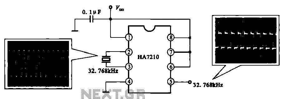
The 32.768 kHz micro-power clock oscillator circuit is designed to provide a stable and low-power clock signal, which is essential for timing applications in electronic devices. The circuit typically employs a crystal oscillator, which utilizes the mechanical resonance of a quartz crystal to produce a precise frequency.
In this configuration, the crystal is connected to an inverter or operational amplifier configured as an oscillator. The output of the oscillator is a square wave clock signal, which can be used to synchronize operations in digital circuits. The low power consumption of this oscillator makes it particularly advantageous for battery-operated devices, ensuring extended operational life.
The circuit should include output terminals that allow for the detection of the clock signal. These terminals enable interfacing with microcontrollers or other digital logic devices that require timing signals. The design may also incorporate decoupling capacitors to filter any noise and ensure stable operation of the oscillator.
Overall, the 32.768 kHz micro-power clock oscillator circuit is a critical component in modern electronic systems, providing essential timing functions while maintaining energy efficiency.Shows a 32.768 kl-b: micro-power clock oscillator circuit, and can be used in mobile phones, laptop computers and home appliances production generates a clock signal supplements. Feet should detect the output clock signal, detecting its feet , feet due oscillator signal.
Related Circuits
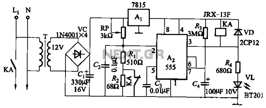
This circuit is applicable in refrigerators and other protective devices. It employs a 7815 three-terminal voltage regulator integrated circuit and an NE555 timer IC configured as a one-shot circuit for delay control. When the voltage drops below 180V, relay...
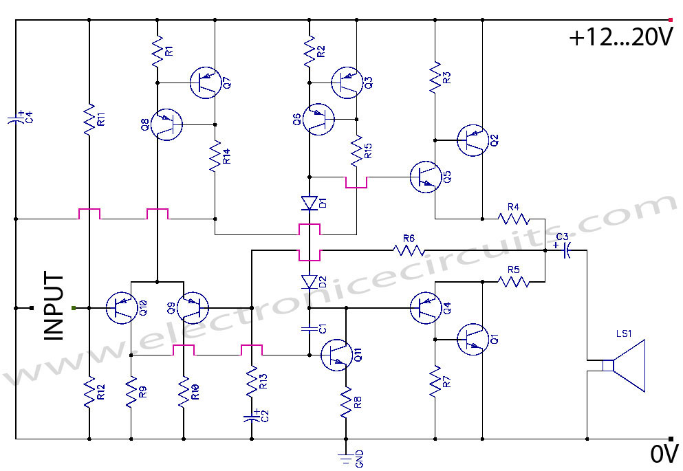
Discrete Class AB Transistor Audio Power Amplifier Circuit Diagram. This is a Class AB transistor power amplifier. It is a simple amplifier to... A Class AB transistor audio power amplifier is designed to provide high-quality amplification for audio signals while...
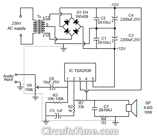
All ground points in the circuit should be connected to a single point and grounded if possible, or connected to the transformer's 0V marked wire as shown in the circuit. In electronic circuit design, proper grounding is crucial for maintaining...
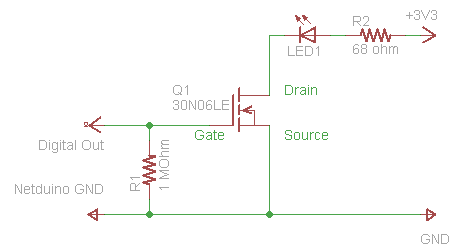
The process of driving an LED involves using a Power MOSFET to control the LED's state (On and Off) via a digital signal. This guide provides a step-by-step approach to wiring the circuit on a breadboard, which serves as...

All of ACC's repeater and remote base products support the control of synthesized remote base transceivers. One form of frequency control supported is compatible with transceivers using thumbwheel frequency selection. The controllers supply BCD (binary coded decimal) formatted data...
The latest addition to the collection of Infrared (IR) Repeater circuits, the Mark 5, is an enhanced version of the Mark 1 circuit and features an increased range. The Mark 5 Infrared Repeater circuit is designed to extend the range...
Warning: include(partials/cookie-banner.php): Failed to open stream: Permission denied in /var/www/html/nextgr/view-circuit.php on line 713
Warning: include(): Failed opening 'partials/cookie-banner.php' for inclusion (include_path='.:/usr/share/php') in /var/www/html/nextgr/view-circuit.php on line 713