
200M FM Transmitter
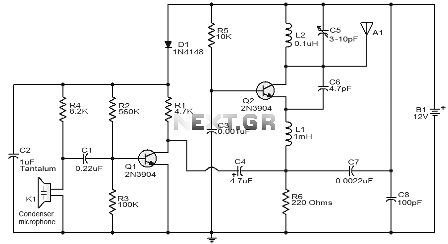
The FM transmitter circuit operates primarily through the interaction of its key components, each serving a specific function to ensure effective sound transmission. The condenser microphone (K1) captures audio signals and converts them into electrical signals. These signals are then processed by the preamplifier stage, constituted by transistor Q1, which amplifies the weak audio signals. The biasing resistors R2 and R3 ensure that Q1 operates in the optimal region of its characteristics, providing sufficient gain without distortion.
The output from Q1 is coupled to the emitter of Q2 through capacitor C4 and inductor L1. Capacitor C4 plays a crucial role in removing any DC offset, allowing only the AC audio signal to pass through to Q2. Transistor Q2 is configured as both an oscillator and modulator. The oscillation is established by the tank circuit formed with inductor L2 and variable capacitor C5, which determines the frequency of the transmitted signal. The feedback capacitor C6 is essential for sustaining oscillations by providing a portion of the output signal back to the base of Q2.
The final modulated FM signal is transmitted through antenna A1, which must be matched to the transmitter for optimal performance. The range of approximately 200 meters can be influenced by factors such as antenna design, transmitter power, and environmental conditions. The inductance calculation formula provided facilitates the construction of the inductor necessary for the circuit, allowing for customization based on the desired specifications. This FM transmitter circuit is suitable for hobbyists and educational purposes, demonstrating fundamental concepts of audio transmission and radio frequency modulation.A very stable and simple FM transmitter circuit is given here. With a matching antenna, this transmitter can attain a range of around 200 meters. I assembled this transmitter few years and got very good results. Let us see how the circuit works. A condenser microphone (K1) is used to pick the sound to be transmitted. Capacitor C1 is a DC decoupler and the sound signal is coupled to the base of Q1 which wired as a preamplifier. R2 and R3 are the biasing resistors of Q1. Amplified sound signal will be available at the collector of Q1 and it coupled to the emitter of transistor Q2 through the capacitor C4 and 1mH inductor L1. Capacitor C4 decouples the DC component from the preamplifier output. Q2 performs the job of oscillator and modulator. Inductor L2 and variable capacitor C5 forms the tank circuit necessary for creating oscillations. Capacitor C6 is the feedback capacitor. The modulated FM wave will be available at the collector of Q1 and it is transmitted using the antenna A1.
This simplified formula will help you in making inductors, L = (d ²n ²) / (18d+40l). Where L is the inductance of the coil in uH, d is the coil diameter in inches, l is the coil length in inches and n is the number of turns. Just try to make the inductor your self using this formaula. If you can`t, then comment here. I will give you the winding details. 🔗 External reference
Related Circuits
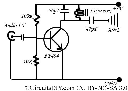
This is a simple and inexpensive FM transmitter. The circuit operates at a low voltage using a CR2025 3V battery with low current consumption. The total size of this FM transmitter, including the battery but excluding the antenna, is...
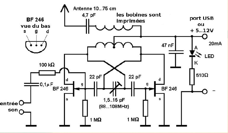
This compact FM transmitter is designed for connection to a USB port and has a range of approximately 50 meters. It can be utilized alongside multiple mini-transmitters to create a diverse and engaging radio program. The power supply through...
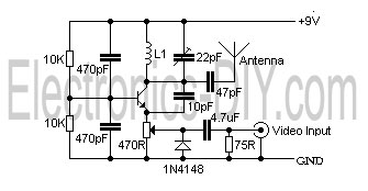
This is a simple video transmitter capable of transmitting signals up to 50 meters. It can be utilized with cameras or other video sources and allows viewing on VHF channel analog televisions. The video transmitter operates on a supply...
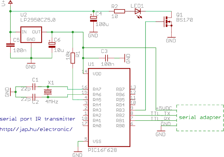
This is a programmable infrared (remote control) transmitter, which can be controlled from a PC serial port. It is capable of sending many remote control formats, including the Philips RC-5 standard. Exact formats with the timing parameter names are...

This is an analog TV transmitter. Sound modulation is of the FM type with a 5.5 MHz carrier frequency, and video transmission follows the PAL standard. The frequency can be adjusted using capacitor C5, allowing tuning from 54 to...
The 2N2222 circuitry is a three-element phase-shift oscillator circuit designed to produce a 1,000 Hz sine wave. This sine wave is subsequently applied to the TCG-610 varactor diode, which has a capacitance of 6 pF at 4 V. The...