
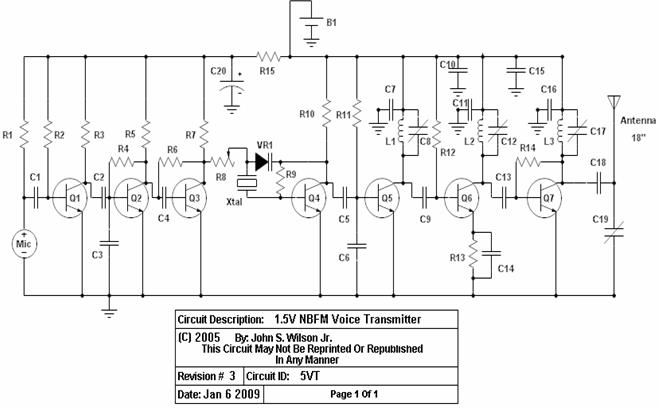
A ONE TRANSISTOR FM TRANSMITTER
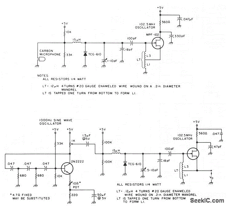
The 2N2222 phase-shift oscillator circuit is a versatile design commonly used in RF applications. It consists of three stages of phase-shifting, typically implemented using RC networks. Each stage contributes to a total phase shift of 180 degrees, with an additional 180 degrees provided by the transistor, allowing for sustained oscillations at the desired frequency.
In this configuration, the 2N2222 transistor operates in the common-emitter mode, where the input signal is applied to the base terminal. The output is taken from the collector, where the sine wave oscillation is generated. The frequency of oscillation is primarily determined by the resistor and capacitor values in the RC networks. For a 1,000 Hz output, careful selection of these components is crucial.
The TCG-610 varactor diode plays a significant role in frequency modulation. By varying the reverse voltage applied to the varactor, the effective capacitance changes, which in turn alters the resonant frequency of the tank circuit. This modulation allows for dynamic frequency adjustments, making the circuit suitable for applications requiring frequency agility.
The inclusion of a 1,000-ohm potentiometer in the collector circuit provides a means to fine-tune the amplitude of the output signal. By adjusting this potentiometer, the user can control the collector current, thereby influencing the overall gain and stability of the oscillator.
Overall, this circuit exemplifies a practical implementation of a phase-shift oscillator using a 2N2222 transistor and a varactor diode, showcasing its functionality in generating a stable sine wave output while allowing for frequency modulation through capacitance variation.The 2N2222 circuitry is a three-element, phase-shift oscillator circuit, designed to yield a 1,000-Hz sine wave. The 1,000-Hz sine wave is then applied to the TCG-610 varactor diode, 6 pF at 4 V, which changes the tank capacitance, thus varying the rf oscillator frequency at a 1,000-Hz rate.
The 1,000-? potentiometer in the collector circuit can be adjusted.. 🔗 External reference
Related Circuits
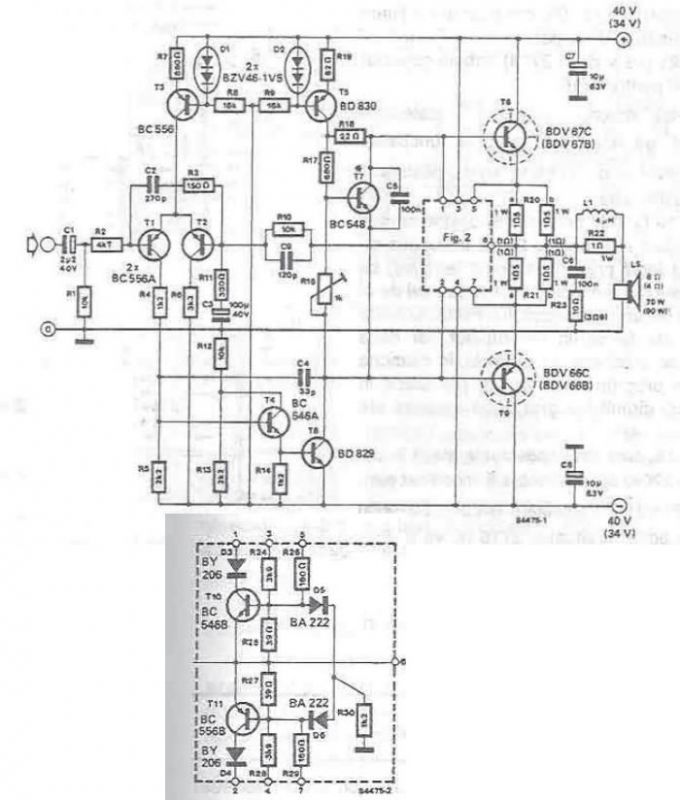
A high-power audio amplifier can be designed using power transistors and other common electronic components, capable of delivering a maximum output power of 90W. When using the specified component values, it can drive speakers with a 4-ohm impedance, resulting...
The power supply varies, and the circuit must operate at under 10 µA of current (excluding the capacitor charging). It triggers a Silicon Controlled Rectifier (SCR) every 10 to 30 seconds as long as the power supply is above...
To test VHF receivers independently from local radio stations, a frequency-modulated oscillator is required, covering the range of 89.5 to 108 MHz. Building such an oscillator with discrete components is challenging. The MAX260x series from Maxim offers five integrated...
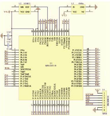
The target designator is designed based on the MSP430F149 microcontroller to facilitate rapid target identification in military training environments. It can adapt to various tactical requirements, allowing for the display of targets and the execution of bomb simulations according...
Construct this circuit utilizing a Digi-Key Electronics Barrel Crystal (CA-301) with a frequency of 15 MHz to achieve a standard output frequency of 150.00 MHz. For frequency customization, follow the provided instructions. Typically, this circuit is designed to operate...
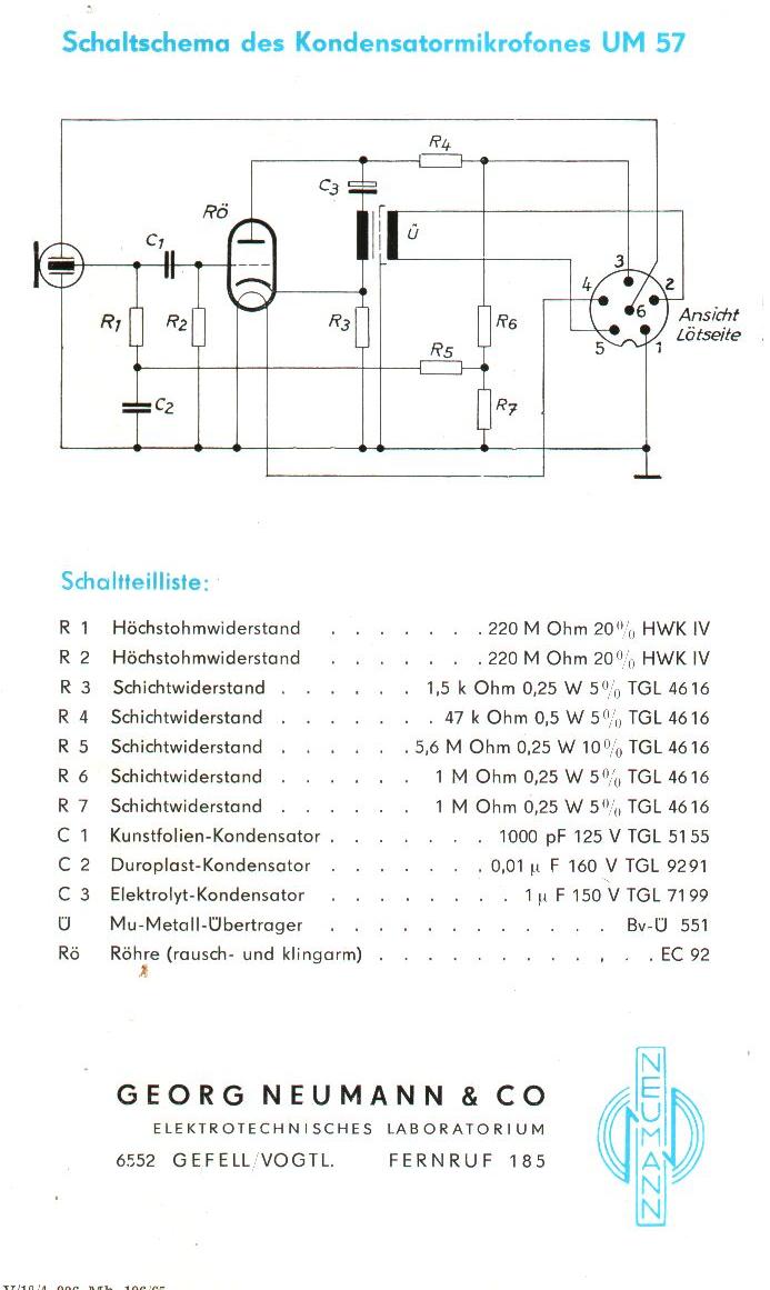
The Neumann/Gefell UM 57 is a large-diaphragm tube condenser microphone produced by the Neumann company in Gefell, Germany, now known as Microtech-Gefell. This microphone features the renowned M7 capsule from Gefell, which is a dual-diaphragm, center-terminated design with a...