
200W 136 kHz transmitter
The output transformer core, identified as A-438281-2-9H9-3, serves a critical role in RF applications, particularly in impedance matching between the transmitter and the antenna. The selection of a transformer core with specific dimensions (47 mm OD, 24 mm ID, and 13 mm height) indicates a deliberate choice to optimize magnetic coupling and minimize losses. The use of an inductive reactance of six times the impedance reflects a design decision aimed at enhancing performance beyond the minimum recommended level, thereby improving efficiency and signal integrity.
The secondary winding's turns ratio of 10 to 30 is essential for achieving the desired impedance transformation from the low impedance output stage (3.3 ohms) to the standard antenna impedance of 50 ohms. This transformation is crucial for maximizing power transfer and minimizing reflections that could degrade performance.
The input stage's capability to handle a signal range of 5 to 12 V peak-to-peak allows for flexibility in signal sources, accommodating both TTL and CMOS signals as well as sinusoidal waveforms. The crystal oscillator's frequency division ensures that the output signal remains within the operational frequency band, which is vital for effective RF transmission.
Thermal management is addressed through the use of a heat sink from a Pentium 2 CPU, which provides adequate dissipation for the MOSFET, preventing thermal overload. The inclusion of a dedicated fan further ensures that the transmitter operates within safe temperature limits, enhancing reliability and longevity.
The choice of bypass capacitors is critical; using high-quality polyester capacitors rated for four times the DC voltage minimizes the risk of failure and ensures stable operation. The configuration of two 1 µF and one 2.2 µF capacitor in parallel optimizes filtering capabilities, effectively decoupling the power supply from high-frequency noise. The emphasis on avoiding electrolytic capacitors and minimizing terminal lengths further contributes to the overall performance and reliability of the circuit, ensuring that parasitic effects are kept to a minimum.Output transformer core: coming from flea market, light blue color, marked as A-438281-2-9H9-3, OD = 47 mm, ID = 24 mm, height = 13 mm. No information about µ Mosfet to be used: coming from flea market, with the following characteristics.
It`s an obsolete (no data sheet could be retrieved) and cheap (1 euro) device and is similar to the well known IRFP450. The ARRL handbook suggests that RF non resonant transformer must have an inductive reactance (XL) at least 4 times the impedance. I decided to use XL= 6 times the impedance. The secondary winding should match the antenna impedance, in my case about 50 ohms. Table 3 report the secondary winding turns, computed with the following formula: The transformer turn ratio (10 / 30) confirms the impedance matching from the 3.
3 ohm of the output stage to the 50 ohm of the antenna system (see formula 3). The input stage can handle a 5 to 12 V pp signal (TTL or CMOS, probably, but not tested, also sinusoidal signals). My Xtal oscillator uses an ex CB Xtal 27. xxx MHz divided by 100. The mosfet is mounted on a heat sink coming from an old Pentium 2 CPU, with the little fan running at 12 V.
Another fan in the box keeps the temperature of the transmitter comfortable; the source pin go to the ground plane directly. The by-pass capacitors C2 e C3 must be of the best quality you can find, rated to 4 times Vdc, I use two 1 µF and one 2, 2 µF polyester 250 volt in parallel.
Don`t use electrolytic capacitors and keep the terminals as short as possible. 🔗 External reference
Related Circuits
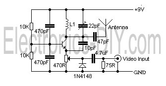
This is a simple video transmitter capable of transmitting signals up to 50 meters. It can be utilized with cameras or other video sources and allows viewing on VHF channel analog televisions. The video transmitter operates on a supply...
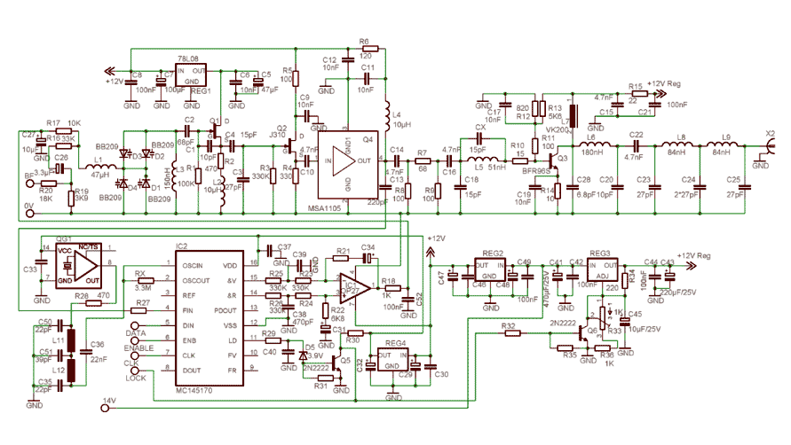
In order to simplify the transmitter design, we've used the new pll circuit from Motorola: the MC145170. This PLL includes the prescaler and a serial standard bus called SPI. We advise to use the P2 version that fixes some...
The first resistor on the left in the schematic is labeled as 68k. This value may change based on the microphone used. In this instance, a microphone from Digi-Key with a 1.5k output impedance was utilized, leading to the...
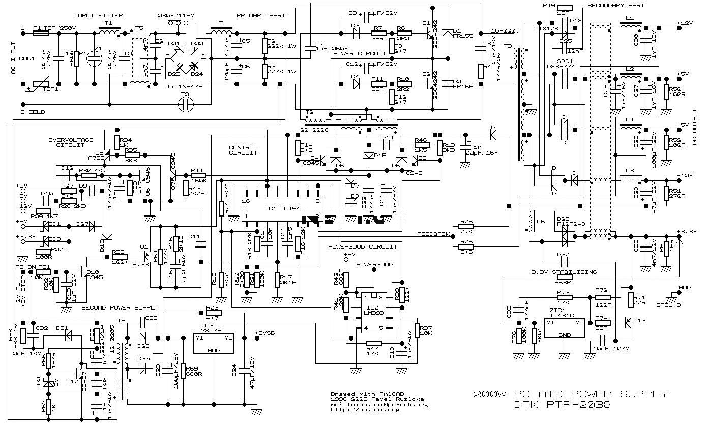
200W ATX Power Supply Circuit power supply. Visit the page for an explanation of the power supply circuit diagram. Here is a simple battery monitor circuit in which the LED continues flashing until the battery voltage is above a...
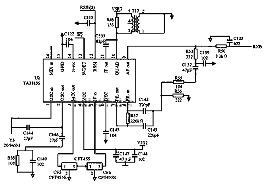
As illustrated in the figure, Vcc is the power supply for the circuit. Upon receiving the initial signal, the frequency is adjusted to 21.7 MHz. This frequency is subsequently enhanced through two crystal filters to improve the selectivity of...
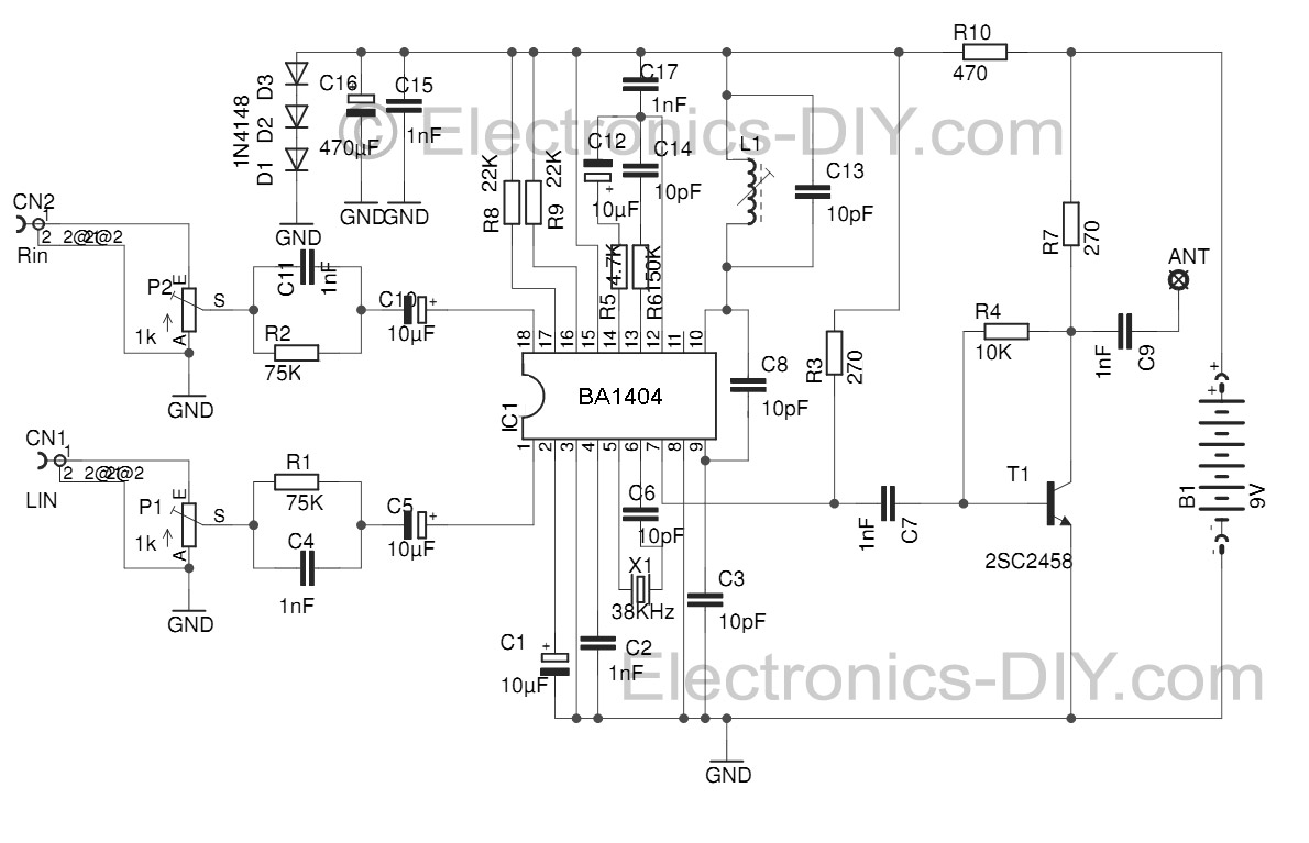
This Stereo FM Transmitter with BA1404 enables the creation of a mini stereo FM station, allowing for wireless audio broadcasting throughout a home. It provides a straightforward method for establishing an audio link without the need for complex wiring....