
Radio reception circuit diagram TA31136
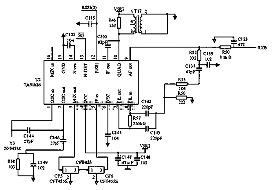
The circuit operates primarily at a frequency of 21.7 MHz, which serves as the main signal frequency. The use of crystal filters is critical in enhancing the selectivity, allowing for the rejection of unwanted frequencies and ensuring that the desired signal is amplified effectively. The transistor Q2 plays a pivotal role in amplifying the selected frequency, and the bias voltage supplied by VCC2 ensures optimal operation of the transistor within its active region.
The TA31136 integrated circuit (U3) is designed for radio frequency applications and is utilized here to mix the 21.7 MHz signal with a local oscillator frequency of 21.245 MHz. This mixing process generates an intermediate frequency of 455 kHz, which is a common frequency used in various communication systems for further processing. The IF amplifier stage is crucial for amplifying the 455 kHz signal before it is demodulated by the frequency discriminator.
The demodulation process involves extracting the original information signal from the modulated carrier wave. The low-pass filter composed of resistor R64 and capacitor C116 effectively removes high-frequency components, allowing only the desired low-frequency signals to pass through, which is essential for producing a clean output signal.
The switch to the Murata ceramic frequency CDB450C24 highlights the importance of component selection in circuit design. The CDB450C24 offers advantages such as compactness, ease of integration, and reliable frequency stability, which are essential for maintaining performance in demanding environments. This choice reflects a thoughtful approach to optimizing the circuit's functionality and reliability. As shown in FIG, Vcc to the circuit is V power supply. After receiving the first signal frequency becomes 21.7 MHz, 21.7 MHz and then after two crystal filter to enhance the se lectivity of the input signal. T10 is the resonant frequency of 21.7 MHz in the week, and the composition of the selected frequency amplifier transistor Q2. VCC2 is 5 V, may provide a bias voltage to the transistor. U3 (TA31136) to 21.7 MHz input signal 16 feet with 1 foot of 21.245 MHz local oscillator signal for mixing, to form a second intermediate frequency 455 kHz.
And then the IF amplifier from 455 kHz frequency discriminator in the week out of the demodulated signal through a low pass filter formed by resistor R64 and the internal composition of the external capacitor C116, filtered intermediate frequency and high harmonics into the low-level circuit. The program before 10 feet and 11 feet out of the part using a frequency discriminator in the week, and found the week coil difficult to debug, and later switched to Muratas ceramic frequency CDB450C24.
Because CDB450C24 simple structure, easy to implement, frequency accuracy of plus or minus 1%, the bandwidth of about 10 kHz, and does not require the load capacitance.
Related Circuits
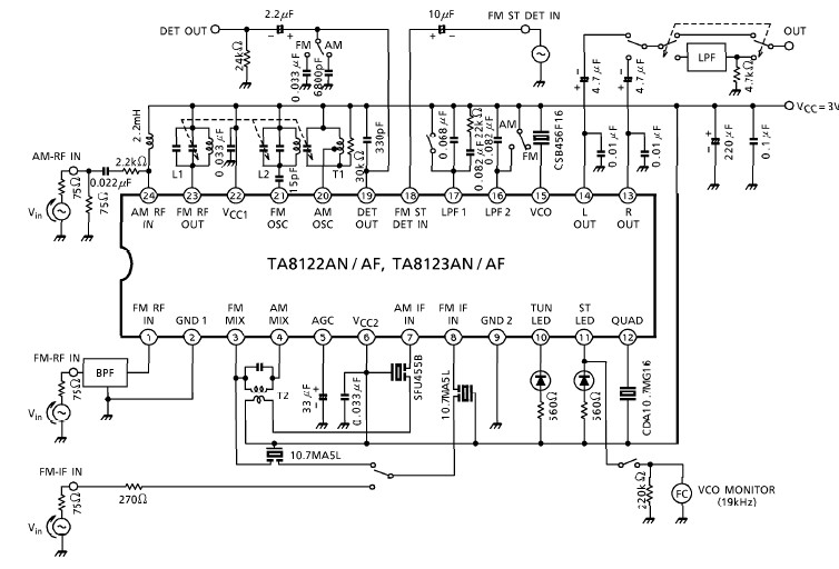
A simple low-power AM/FM radio receiver electronic project can be designed using the TA8122 integrated AM/FM receiver, manufactured by Toshiba Semiconductor. This radio receiver circuit can be utilized for portable radio applications or similar devices. The TA8122 radio receiver...
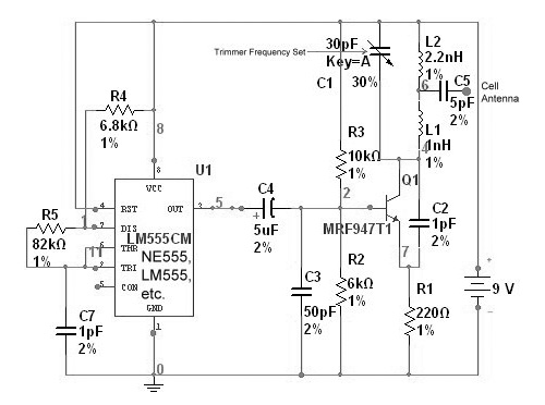
The circuit is based on the NE555 timer, functioning as a simple noise maker, with its output connected to a single transistor oscillator. This oscillator is designed to operate within a frequency range of 800 MHz to 2 GHz,...
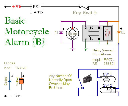
These are two easy-to-build relay-based alarms. They can be used to protect a motorcycle, but they have many additional applications. When using relays with 6-volt coils, they can safeguard a classic bike. Both alarms are compact, with completed boards...
It is essential to consider migrating to PIC microcontrollers and exploring compilers such as those offered by Proton Smart, which include Sony IR and Philips RC5 codecs. This approach is particularly advisable for security-sensitive applications. Additionally, Bluetooth and Wi-Fi...
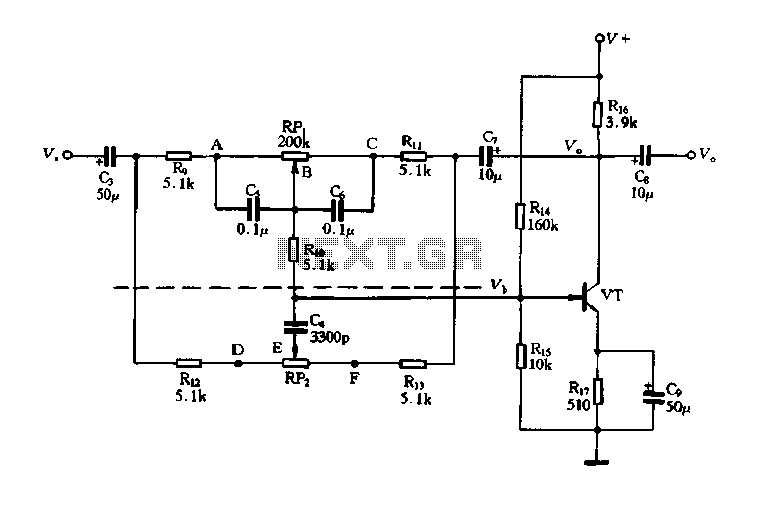
The circuit is a decay feedback tone control circuit that incorporates anti-attenuation feedback action. Its primary function is to enhance or attenuate bass frequencies, although this distinction can sometimes be challenging to perceive. The analysis utilizes the superposition theorem,...
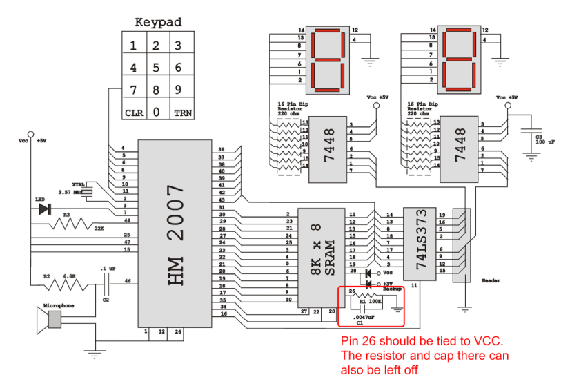
Verify the pin configurations on the datasheets for the integrated circuits used in your project, making necessary adjustments. In this instance, the RAM chip utilized had a non-inverted enable signal on pin 26, while the schematic assumed it was...
Warning: include(partials/cookie-banner.php): Failed to open stream: Permission denied in /var/www/html/nextgr/view-circuit.php on line 713
Warning: include(): Failed opening 'partials/cookie-banner.php' for inclusion (include_path='.:/usr/share/php') in /var/www/html/nextgr/view-circuit.php on line 713