
20w rf fm amplifier circuit
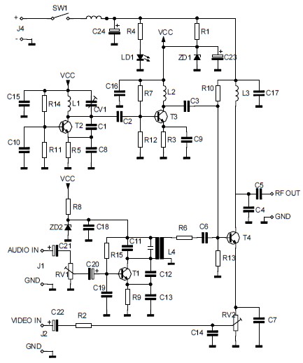
The FM RF amplifier circuit is designed for high-frequency applications, specifically targeting the FM broadcast band. The BLV 10 and BLW 87 transistors are selected for their high-frequency performance and low noise characteristics, which are essential for maintaining signal integrity in FM transmission. The Class C configuration is advantageous for amplifying modulated signals, as it allows for high efficiency and good linearity, making it suitable for RF amplification.
The gain of 21 dB indicates that the output signal is 100 times stronger than the input signal, which is crucial for ensuring that the transmitted signal can cover a sufficient distance without significant degradation. The efficiency range of 55-65% reflects the power conversion effectiveness of the amplifier, indicating that a substantial portion of the input power is converted into useful output power.
The low-pass filter composed of nine components plays a critical role in minimizing unwanted harmonics from the output signal. By achieving 60 dB of attenuation on the second harmonic, the design significantly reduces the potential for interference with adjacent channels, thereby enhancing the overall performance of the amplifier in a crowded frequency spectrum.
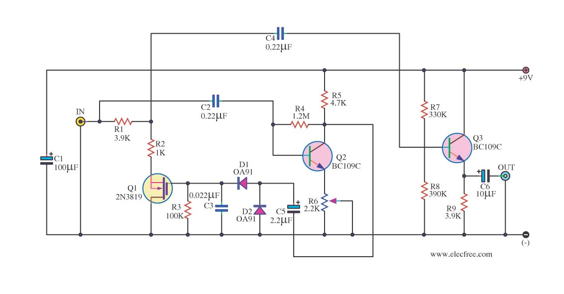
In summary, this FM RF amplifier is a well-engineered solution for broadcasting applications, effectively amplifying signals within the designated frequency range while maintaining high efficiency and minimizing harmonic distortion.This Fm rf ability amplifier has 2 transistors from Philips : BLV 10 and BLW 87. The 2 rf transistors assignment in chic C and this fm amplifier has a absolute accretion of 21dB ( 100 X ) and ability 55 65%. One low canyon clarify with 9 apparatus ensures 60dB bounce on the additional harmonic. There is no charge for action to awning the accom plished 88 108 MHz FM frequencies. 🔗 External reference
Related Circuits
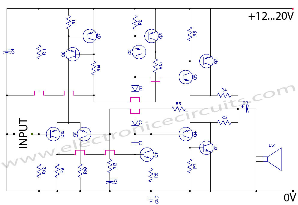
Discrete Class AB Transistor Audio Power Amplifier Circuit Diagram. This is a Class AB transistor power amplifier. It is a simple amplifier to... A Class AB transistor audio power amplifier is designed to provide high-quality amplification for audio signals while...
The circuit converts audio and video signals into a UHF TV signal, allowing a video signal from a camera or other source to be connected to a standard TV set. The audio and video signals are transformed into a...
The circuit diagram presented illustrates an IC-controlled emergency light with a charger, functioning as a 12V to 220V AC inverter circuit. This emergency light circuit is designed to automatically activate in the event of a mains failure, while also...
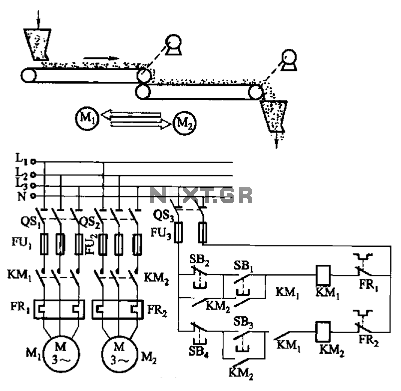
The circuit depicted in Figure 3-86 utilizes a line utilization time relay to control two motors, starting one before the other after an initial stall. The time relay KTi can be adjusted to modify the starting interval of the...

This is an analog TV transmitter. Sound modulation is of the FM type with a 5.5 MHz carrier frequency, and video transmission follows the PAL standard. The frequency can be adjusted using capacitor C5, allowing tuning from 54 to...
In audio systems, noise signals are generally undesirable, and efforts are often made to eliminate them. Transistors can be utilized effectively for this purpose due to their availability and low noise characteristics. The following circuit serves as a Noise...