
Audio noise filter circuits

The Noise Filter Circuit described is an effective solution for mitigating unwanted audio interference. The choice of the 2N3819 FET transistor is strategic, as it provides a low-noise operation essential for maintaining audio fidelity. The TL071 operational amplifier is well-suited for this application due to its high input impedance and low output distortion, allowing for accurate signal processing.
The design incorporates a band rejection filter configuration, which is crucial for targeting specific frequency ranges that may introduce noise into the audio signal. The calculated values for the resistors and capacitors are critical in determining the filter's cutoff frequency and overall performance. The formula \( F = \frac{1}{2\pi RC} \) is used to derive the cutoff frequency, ensuring that the circuit effectively rejects frequencies around 50 Hz, a common range for unwanted noise.
The inclusion of a switchable feature for Rumble and Scratch noise allows users to customize the filtering process according to their specific needs. This flexibility is beneficial in various audio environments where different types of noise may be present. The recommendation to use a 9V battery as a power source is particularly important, as it helps to minimize power supply noise, which can otherwise affect the overall performance of the audio system.
In summary, this Noise Filter Circuit is a practical and efficient solution for audio applications, providing users with the ability to filter out undesirable noise while preserving the integrity of the desired audio signal.When we said to Noise signal in an audio system. everyone not likes it, wants to get rid of it all. I also not like them too. However, we can use it to get rid of it. I use transistors. Because it is easy to find. And low noise. Friends try to see the circuit below. This be Noise Filter Circuit for filter the frequency disturbs all well. By use ba se type equipment the FET transistor number 2N3819 and Electronic part The other a little again. It can be usable economize with. By the circuit will decrease frequency tall signal more 20KHz well. Then can apply in side sound circuit well, and still have still can fine decorate filter noise level has as well yes. The band rejection filter circuit is not wide filter that can denial the frequency up to 60dB by we used the TL071 single chip op-amp it is very low distortion and work good at output to maximum to 100kHz or the range 1Hz to 20kHz In the circuit we defined three resistors R1, R2, R3 are like value to 100K, and then two capacitors C1, C2 are equal to 330pF, For will reject the frequency at 50Hz.
By we can select the parts with the formula is F = 2G—3. 14xRC, And to get rejection well than 40dB if we should the resistor matched to 0. 1% and capacitor to 1%. If a friend gets into trouble about the noise. Try out this circuit before, may like. It is Filter the Scratch and Rumble Noise Circuit. That make a friend feels annoyed very the character of the circuit filters this frequency, use, Resistor, and, Capacitors, or, RC Filter that often call that Passive Filter Circuit. By have Switch choose filter the noise. By SW1 for Rumble noise Filter and the SW2 for Scratch noise filter. Make the noise that change this circuit goes to are left a little for power supply Source should use battery 9V.
Because will decrease the noise from power supply, give with this circuit there yes. 🔗 External reference
Related Circuits
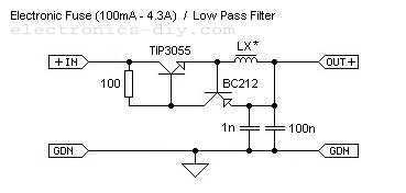
This is adjustable electronic fuse that can be used to protect power supplies from short circuits or can be also used to limit the current usage. It can be adjusted for currents from 100mA up to 4.3A. An adjustable electronic...
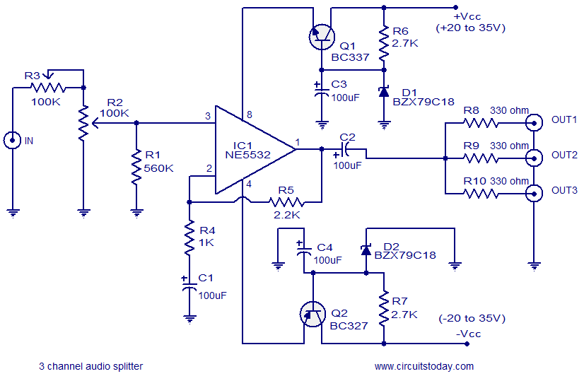
The circuit diagram illustrates a simple 3-channel audio splitter utilizing the NE5532 integrated circuit. The NE5532 is a dual, internally compensated low-noise operational amplifier produced by Fairchild Semiconductors. It features a high small-signal and power bandwidth, making it ideal...
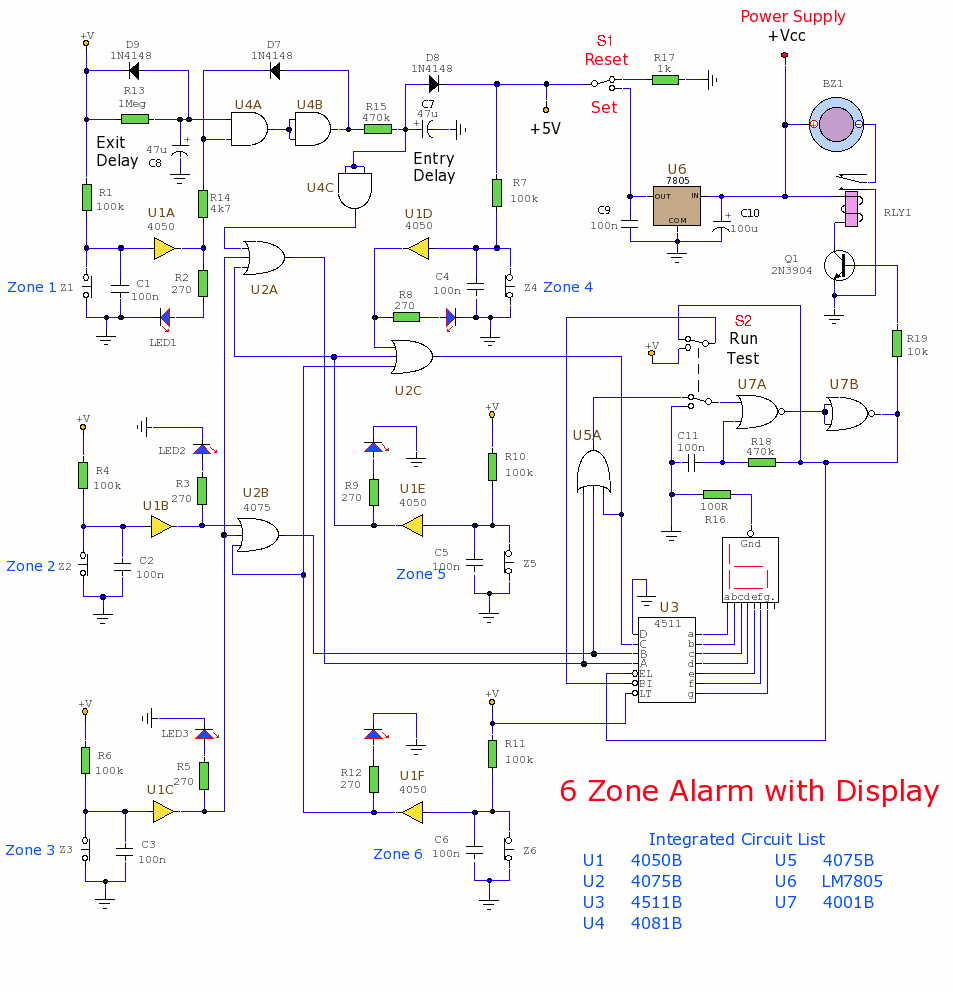
This section includes intruder alarms for homes, cars, and motorcycles, as well as power failure alarms, water level alarms, and a snore detector. All circuits are organized alphabetically on the Circuit Index page and chronologically on the update page....
It is advisable to modify inexpensive USB speakers to obtain a pre-assembled analog front-end for this project. If this is not feasible, then soldering will be necessary, requiring a minimum of two resistors and one capacitor, assuming the display...
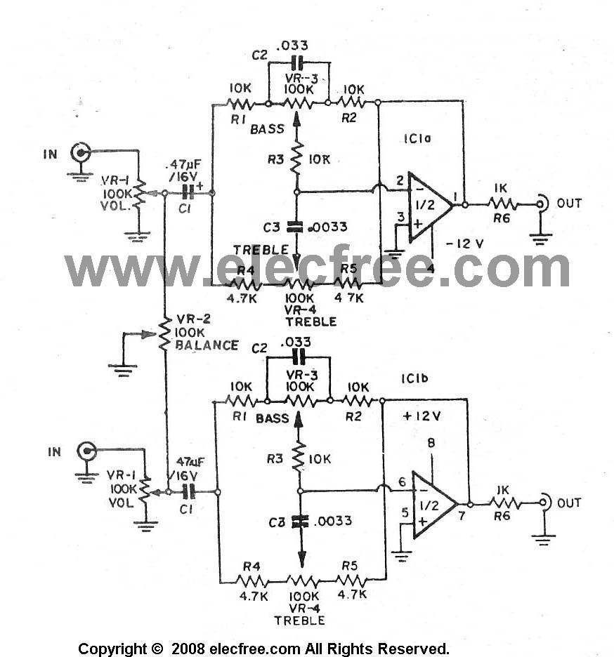
A high-quality preamplifier with tone controls consisting of three circuits. The NE5532 is chosen as the main integrated circuit due to its ultra-low noise properties, making it a popular choice in fine audio applications. Although these circuits are older...
The internal mute circuit and pre-set gain resistors provide a cost-effective design solution. Output power specifications at both 20V and 24V supplies, along with a low external component count, offer significant value to consumer electronic manufacturers for stereo TV...