
22 Watts Mini Subwoofer Circuit TDA1516 with Adjustable Frequency
The TDA1516 amplifier circuit is designed for optimal performance in automotive applications, where space and efficiency are critical. The BTL configuration allows for higher power output without requiring a transformer, making it a cost-effective solution for driving subwoofers. The use of dual-linear motion potentiometers enables precise control over the volume and frequency response of the subwoofer, allowing the user to tailor the audio experience to their preference.
The inclusion of the dual BIFET Op-Amp enhances the overall audio fidelity by providing low noise and high input impedance, which is essential for maintaining signal integrity. The RCA audio input ensures compatibility with standard car audio systems, allowing for straightforward installation and integration.
The isobaric configuration of the woofers improves efficiency and reduces the required enclosure size, making it an ideal choice for compact automotive environments. The low-pass filter designed with IC1B effectively attenuates frequencies above the desired cutoff point, ensuring that only low frequencies reach the subwoofer, which is crucial for preventing distortion and enhancing the listening experience.
The voltage stabilizer formed by Q1, Q2, R17, and C9 plays a vital role in maintaining consistent performance by filtering out any voltage fluctuations that could adversely affect the amplifier's operation. This careful consideration of component selection and circuit design results in a robust and reliable subwoofer amplifier suitable for various automotive audio applications.The subwoofer is a subwoofer or a speaker to reproduce low frequencies, devotee of 20 Hz to 150 Hz electronic circuit diagram below shows the details of a scheme of the main amplifier TDA1516 22 watt in 4 ohm car subwoofer driver. This device is designed for an existing stereo amplifier, often requires adding another blow to the music of driving a
subwoofer. The amplifier uses BTL is a good and cheap (Bridge Tied Load channels) 13-pin IC TDA1516 from Philips is now NXP Semiconductors), which may provide a small number of components and 22W at 4 ohm load voltage 12 volt car battery default. The device consists of several parts: the name of the potentiometer, dual-linear motion potentiometers, 1/4W resistors, capacitors, electrolytic 25V, 63V Polyester capacitors, LED, 100 mA NPN transistor, dual BIFET Op-Amp, 24 W BTL car radio RCA audio input amplifier and two speakers 4 ohm or 8 ohm woofers in isobaric parallel wiring.
The signals from the line outputs for stereo mixing amplifier input drive, and taking into account the level of the signal to the buffer and can be reversed IC1A phase SW1. Such control may be useful to the subwoofer in phase with the speaker of the existing car radio. Then, a variable frequency 12dB/octave-pass low IC1B, the components of the Q1 and then you can pass the low frequency of 70 Hz or 150 Q2, R17 and C9 form a voltage stabilizer to facilitate access and filtering circuit to prevent track of the services given power at a low level positive.
🔗 External reference
Related Circuits
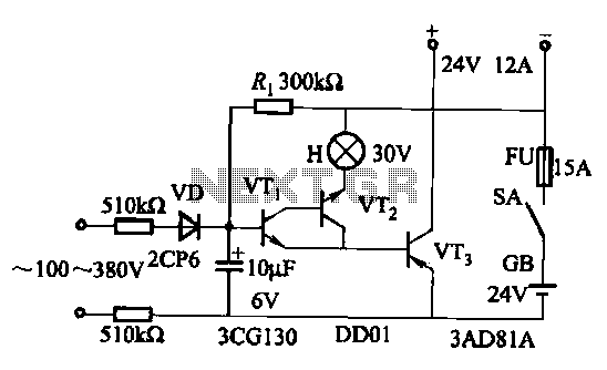
An AC-DC power supply without a power switching circuit is typically employed in lighting load circuits. When the power grid is restored, the standby power supply automatically switches on. The automatic switching circuit utilizes a transistor, as illustrated. The...
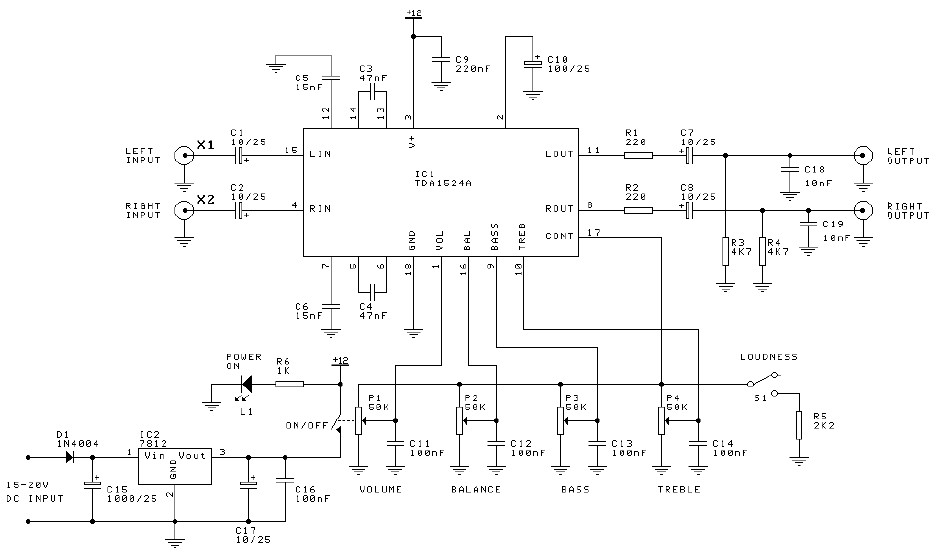
Preamplifier and tone control circuit based on the TDA1524A. The tone control circuit module is included in this preamplifier circuit, allowing for direct connection of the output channels to a stereo power audio amplifier circuit. This RIAA stereo preamplifier...
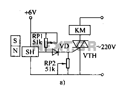
The automatic weapon features a magnetic switch circuit that is simple, reliable, has a low failure rate, and offers good versatility. It can be used for output performance or converted into mechanical displacement applications. The circuit diagram utilizes a...
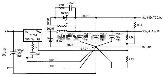
Input voltages can range from 8 V to 30 V. The load range for the 5 V output is from 0.05 A to 5 A, while the load range for the 3.3 V output is from 0.1 A to...
A schematic of a flip-flop LED flashing circuit is presented. This circuit functions as an astable multivibrator that activates LEDs sequentially upon power application. It is compatible with voltage inputs ranging from 6 to 12 volts, and can also...
A crystal oscillator circuit is a straightforward oscillator circuit that can be easily understood through its schematic diagram. It serves as a replacement for a conventional oscillator network, which typically consists of an LC combination. This simplicity is also...