
flip flop led flashing circuit
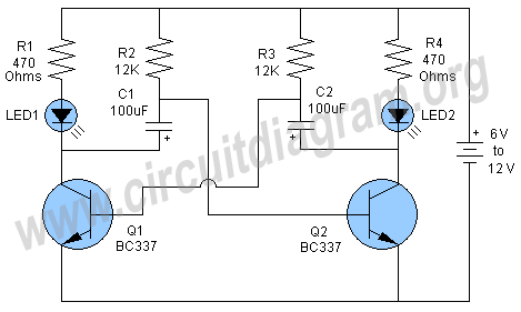
The flip-flop LED flashing circuit operates as an astable multivibrator, creating a continuous square wave output that alternates between high and low states. When power is applied, the circuit initiates a sequence where the LEDs blink one after another, producing a visually appealing effect. The design is versatile, allowing for operation across a range of voltages from 3 to 12 volts, making it suitable for various applications and power supply configurations.
The timing characteristics of the flashing LEDs can be fine-tuned by adjusting the resistance and capacitance values in the circuit. Resistors R2 and R3, along with capacitors C1 and C2, determine the frequency of the oscillation, thus controlling how quickly the LEDs flash. For example, increasing the resistance or capacitance will slow down the flashing rate, while decreasing these values will speed it up.
The circuit utilizes two BC337 NPN transistors, which are key components for switching the LED states. These transistors are capable of handling moderate current levels, making them suitable for driving standard LEDs. However, other NPN transistors such as the 2N2222 and 2N4401 can be substituted without significant changes to the circuit's performance. This flexibility in component choice allows for easy sourcing and customization based on availability and specific project requirements.
Overall, this flip-flop LED flashing circuit is an excellent project for both beginners and experienced electronics enthusiasts, providing a practical demonstration of multivibrator operation and LED control while allowing for various configurations and adjustments.A very interesting schematic of Flip flop LED flashing circuit. The circuit actually is an astable multivibrator which starts blinking LEDs one by one when power is applied. This LED flasher circuit can be operated with any voltage from 6 to 12 volts, you can also operate the circuit with 3, 4 or 5 volts The flashing rate of the circuit can be inc
reased or decreased by changing the values of R2, R3, C1 and C2. The circuit is using two general purpose BC337 NPN transistors but you can also use other transistors for example 2N2222 and 2N4401 etc. 🔗 External reference
Related Circuits
Safety polarity connection circuit design using common electronic components The safety polarity connection circuit is designed to ensure that electronic devices are connected with the correct polarity, preventing damage from reversed connections. This circuit typically employs common electronic components such...
A circuit that utilizes one cycle of alternating current (AC) to produce direct current (DC). A half-wave rectifier circuit generates DC from either the positive or negative cycle of the AC input, but not both. It is important to...

Most homes today have at least a few infrared remote controls, whether for the television, video recorder, stereo, or other devices. Despite this, many individuals have experienced frustration when a light remains on after settling into a comfortable chair...
A company has developed an intelligent temperature monitoring system using the ATMET 89C51 microcontroller. This system automatically records temperature data for a three-phase power supply, including high temperature and other relevant data, functioning as a black box. The ATMET...
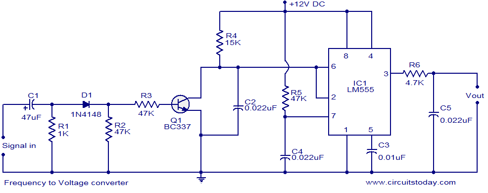
A simple frequency to voltage (F to V) converter circuit utilizing the LM555 Timer IC. This circuit has numerous applications in digital frequency meters, tachometers, and other related devices. The frequency to voltage (F to V) converter is a crucial...
1 kHz RC phase shift oscillator circuit The 1 kHz RC phase shift oscillator circuit is designed to generate a continuous sine wave output at a frequency of 1 kHz. This circuit typically utilizes a combination of resistors and capacitors...