
24hr clock using logic ics
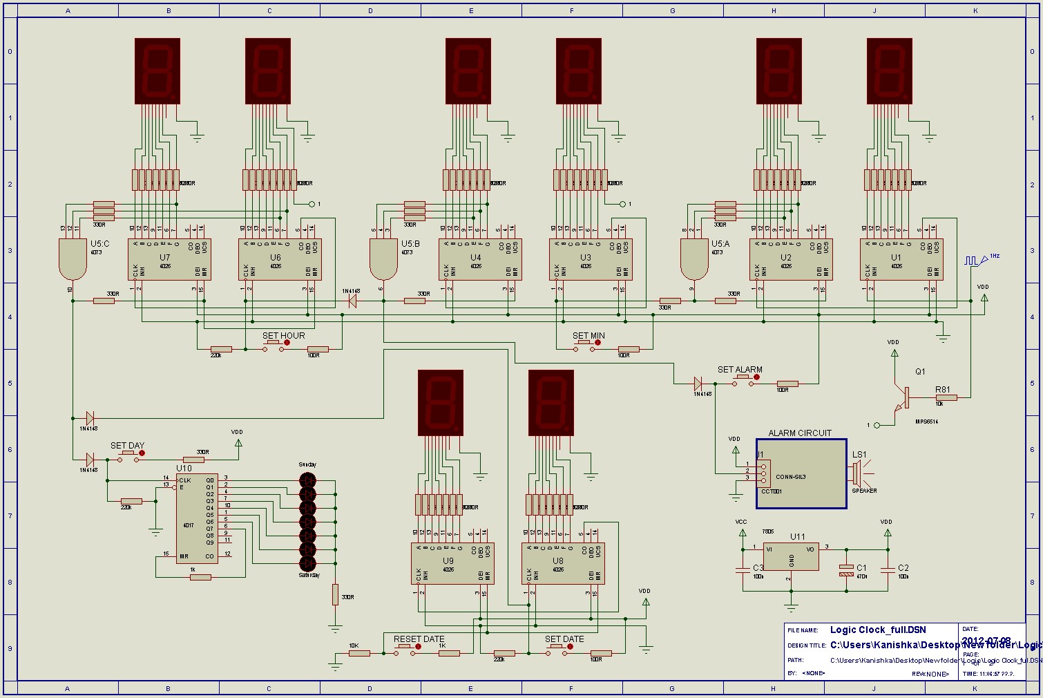
The circuit described is based on a decade counter, typically implemented with a 4017 decade counter IC, which counts from 0 to 9 in response to clock pulses. The clock input is essential for advancing the count, and the rising edge of the clock signal triggers the counting action. Outputs Q0 through Q9 are used to indicate the current count, activating sequentially with each clock pulse. The use of diodes to combine outputs for specific sequences allows for flexible applications, such as creating visual effects with LED displays.
The reset function is critical for initializing the counter or for setting specific counting ranges. By connecting an output to the reset pin, the counting can be limited, allowing for applications that do not require a full decade count. The disable input serves as a control mechanism to pause counting, which can be useful in scenarios where the count needs to be held constant temporarily.
The G·10 output is particularly useful for cascading multiple counters, enabling the design of more complex counting systems. This output effectively divides the clock frequency by ten, making it suitable for driving additional decade counters.
The display control inputs—enable display and disable clock—provide user control over the visibility of the count and the counting process itself. These features enhance the versatility of the circuit, allowing it to be adapted for various applications, including digital clocks, scoreboards, and other counting devices.
In summary, this circuit provides a robust solution for counting applications, featuring multiple control inputs for flexible operation, and is capable of driving displays directly, making it suitable for a wide range of electronic projects.The count advances as the clock input becomes high (on the rising-edge). Each output Q0-Q9 goes high in turn as counting advances. For some functions (such as flash sequences) outputs may be combined using diodes. The reset input should be low (0V) for normal operation (counting 0-9). When high it resets the count to zero (Q0 high). This can be do ne manually with a switch between reset and +Vs and a 10k resistor between reset and 0V. Counting to less than 9 is achieved by connecting the relevant output (Q0-Q9) to reset, for example to count 0, 1, 2, 3 connect Q4 to reset. The disable input should be low (0V) for normal operation. When high it disables counting so that clock pulses are ignored and the count is kept constant. The G·10 output is high for counts 0-4 and low for 5-9, so it provides an output at 1/10 of the clock frequency.
It can be used to drive the clock input of another 4017 (to count the tens). The count advances as the clock input becomes high (on the rising-edge). The outputs a-g go high to light the appropriate segments of a common-cathode 7-segment display as the count advances. The maximum output current is about 1mA with a 4. 5V supply and 4mA with a 9V supply. This is sufficient to directly drive many 7-segment LED displays. The table below shows the segment sequence in detail. The disable clock input should be low (0V) for normal operation. When high it disables counting so that clock pulses are ignored and the count is kept constant. The enable display input should be high (+Vs) for normal operation. When low it makes outputs a-g low, giving a blank display. The enable out follows this input but with a brief delay. The G·10 output (h in table) is high for counts 0-4 and low for 5-9, so it provides an output at 1/10 of the clock frequency.
It can be used to drive the clock input of another 4026 to provide multi-digit counting. 🔗 External reference
Related Circuits
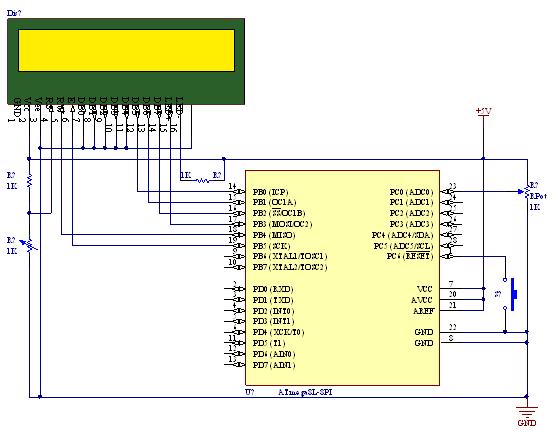
A straightforward tutorial on utilizing the ADC (Analog to Digital Converter) unit of the AVR microcontroller, demonstrated with the Atmega8, including a circuit diagram and code examples. The ADC unit in the Atmega8 microcontroller is a crucial component that allows...
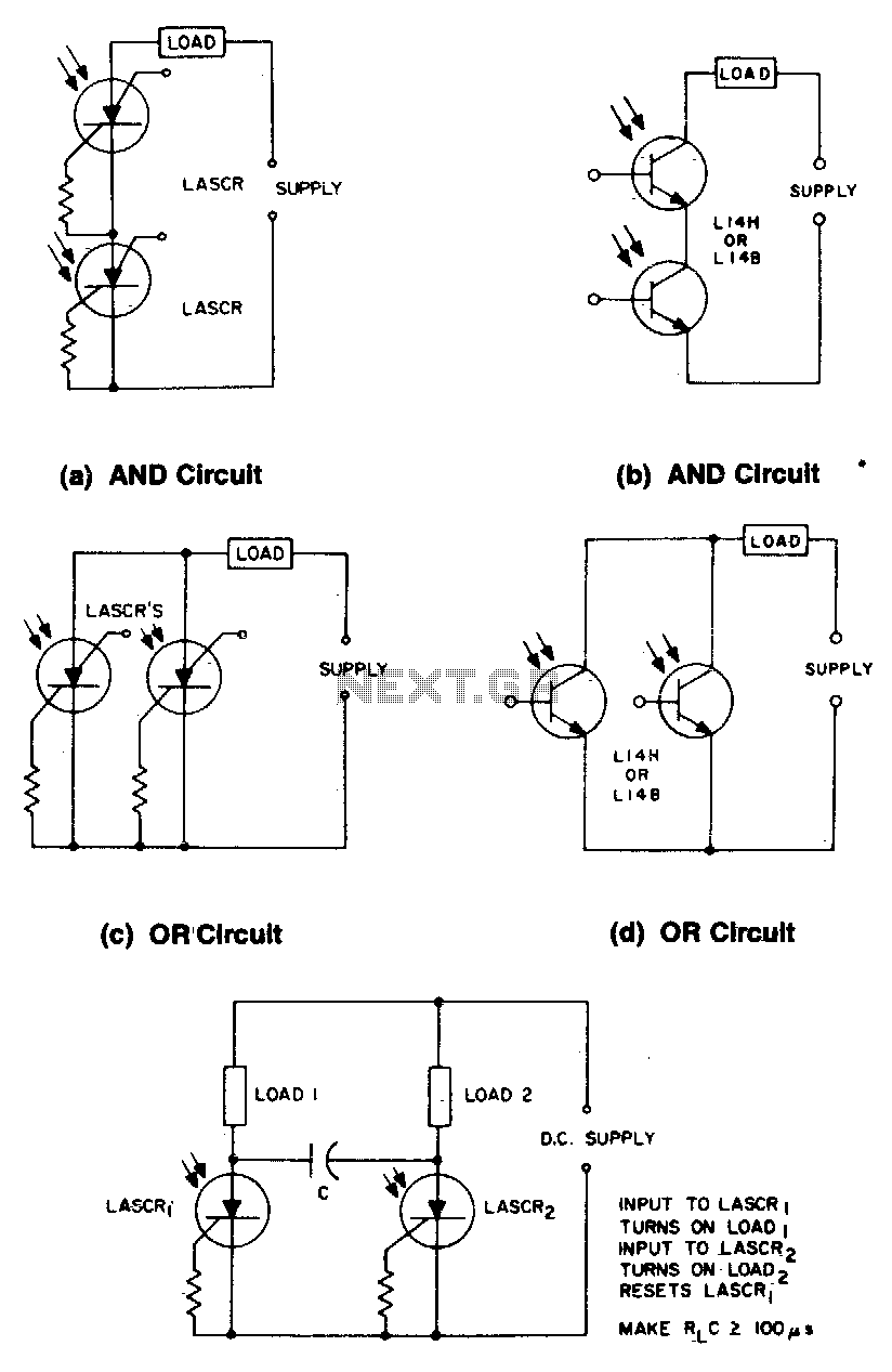
These circuits illustrate some of the common logic functions that can be implemented. The provided circuits serve as examples of fundamental logic functions utilized in digital electronics. Logic functions are the building blocks of digital systems, enabling the execution of...
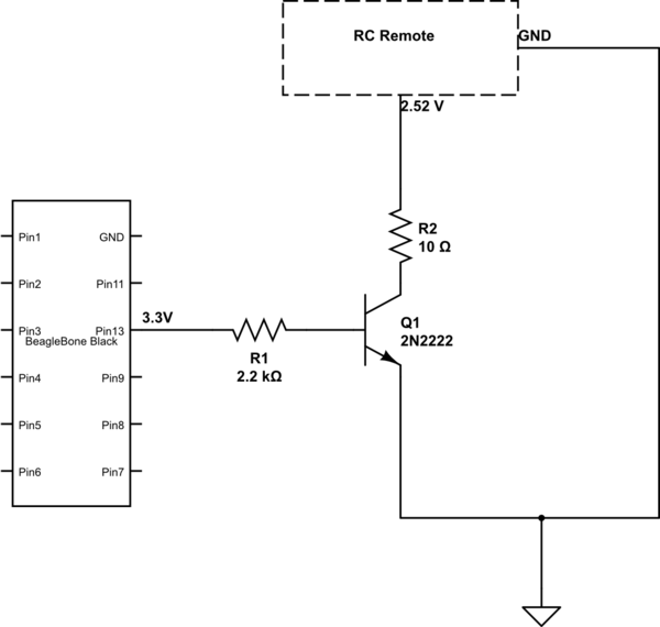
The remote control of an RC car was modified by extending wires from the backward, forward, left, and right switches. Grounding any of these wires completes the circuit and sends a signal to the car. The intention is to...
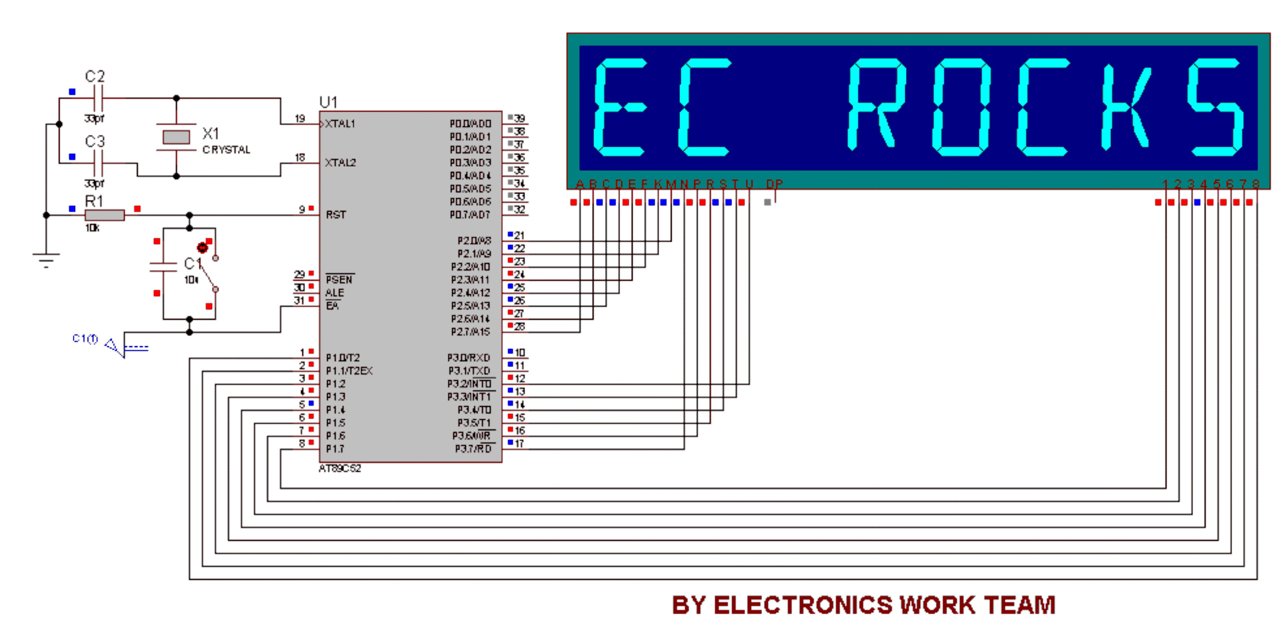
This circuit utilizes a 14-segment display to represent characters. The 14-segment display consists of 22 pins, which facilitate the display of various characters. Eight pins labeled A, B, C, D, E, F, K, and M are connected to the...
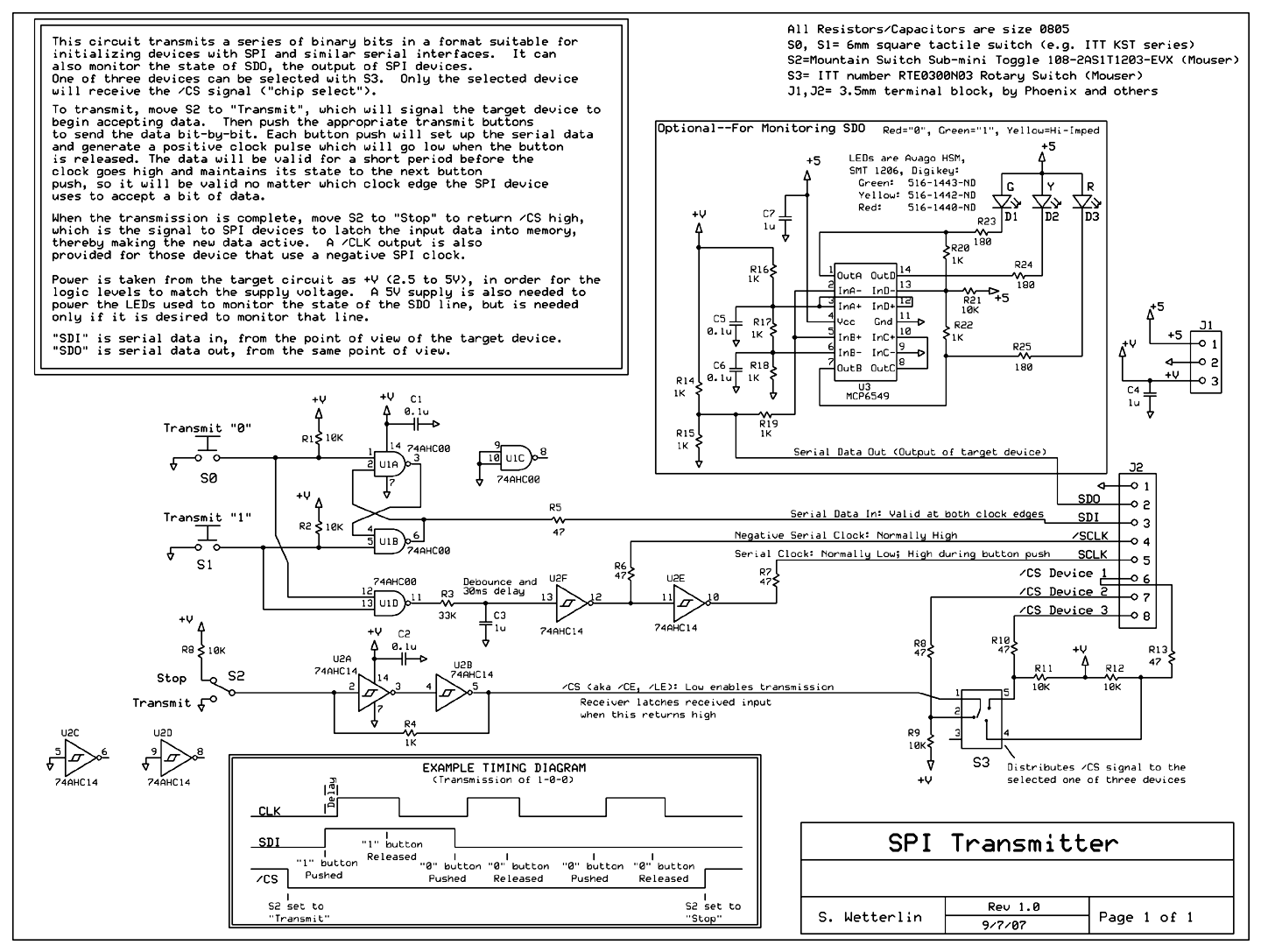
Schematic for the SPI Supplies Faraday Cup. This document provides a detailed examination of the diagrams for the SPI Supplies stand-alone Faraday Cup, which is utilized for calibrating beam currents in wavelength dispersive electron microprobes, as well as interfacing...
This mini logic analyzer is a tool that allows users to observe the logic transitions (0 or 1) of a digital data signal on an LCD display. Such digital data signals can be found on the output pin of...