
24V lead acid battery charger circuit
The lead-acid battery charger circuit operates by converting the AC mains voltage into a regulated DC output suitable for charging lead-acid batteries. The LM317 voltage regulator is pivotal in this circuit, providing adjustable output voltage and current limiting capabilities. The charging current, set at 700mA, is appropriate for maintaining the health and longevity of the batteries while preventing overcharging.
The transformer T1 is selected based on its secondary voltage rating, which must be sufficient to provide the required charging voltage after rectification and filtering. The bridge rectifier D1 converts the AC voltage to DC, and the filter capacitor C1 smooths the output, ensuring a steady voltage level for the batteries.
Resistor R3 is crucial for setting the voltage level, while the potentiometer R4 allows for fine adjustments to achieve the desired charging voltage of 28V, which is suitable for two 12V batteries in series. The inclusion of diode D1 is essential for protecting the circuit from back EMF generated by the batteries during disconnection or power loss.
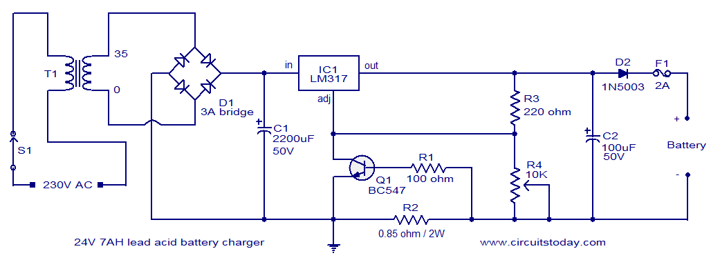
This charger design emphasizes safety and efficiency, ensuring that the batteries are charged correctly while minimizing the risk of damage. Proper assembly and calibration of the circuit components will yield a reliable charging solution for lead-acid batteries, making it suitable for various applications where such batteries are utilized.This lead acid battery charger circuit is designed in response to a request from Mr. Devdas. C. His requirement was a circuit to charge two 12V/7AH lead acid batteries in series. Anyway he did not mentioned the no of cells per each 12V battery. The no of cells/battery is also an important parameter and here I designed the circuit assuming each 12V b attery containing 6 cells. When two batteries are connected in series, the voltage will add up and the current capacity remains same. So two 12V/7AH batteries connected in series can be considered as a 24V/7AH battery. The circuit given here is a current limited lead acid battery charger built around the famous variable voltage regulator IC LM 317.
The charging current depends on the value of resistor R2 and here it is set to be 700mA. Resistor R3 and POT R4 determines the charging voltage. Transformer T1 steps down the mains voltage and bridge D1 does the job of rectification. C1 is the filter capacitor. Diode D1 prevents the reverse flow of current from the battery when charger is switched OFF or when mains power is not available. To setup the charging voltage, power ON the charger and hook up a voltmeter across the output terminals and adjust R4 to make the voltmeter read 28V.
Now the charger is ready and you can connect the batteries. 🔗 External reference
Related Circuits
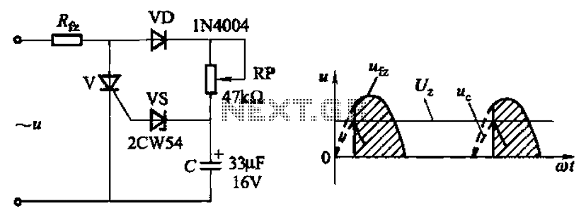
Circuit characteristics: A simple phase shift range of 180 degrees; exhibits good linearity and control accuracy compared to the first two options, making it suitable for low voltage applications, particularly in less demanding electroplating and electrolysis power supplies. The described...
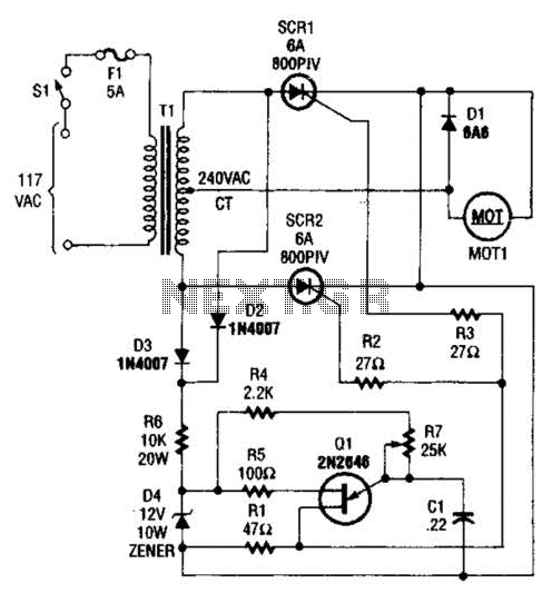
A center-tapped 240-V transformer is used with two SCR devices to provide rectified AC (pulsating DC) to MOT1. Q1 is a UJT ramp generator used to generate trigger pulses for SCR1 and SCR2. The circuit employs a center-tapped transformer rated...
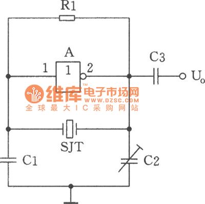
The image depicts a sine wave oscillator that consists of a quartz crystal (SJT) and gate A of the hex inverter IC CD4069. Compared to a standard RC phase-shift oscillator, the frequency stability of a crystal oscillator can achieve...
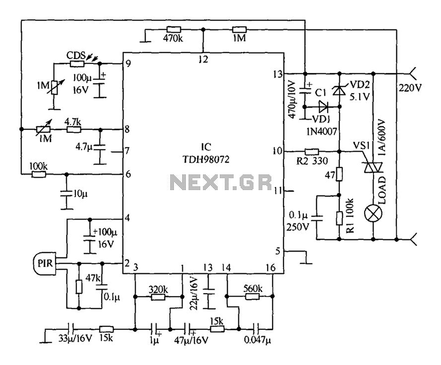
The circuit primarily consists of a new pyroelectric infrared sensor device, TDH98072, which features a special composition. This device is integrated with a control circuit characterized by simplicity, ease of adjustment, and high reliability. Additionally, the device can be...
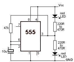
This LED flasher circuit utilizes the 555 timer integrated circuit (IC). The circuit diagram is straightforward and requires only a few external components. When operational, the red LEDs will flash sequentially at a predetermined frequency, similar to the indicators...
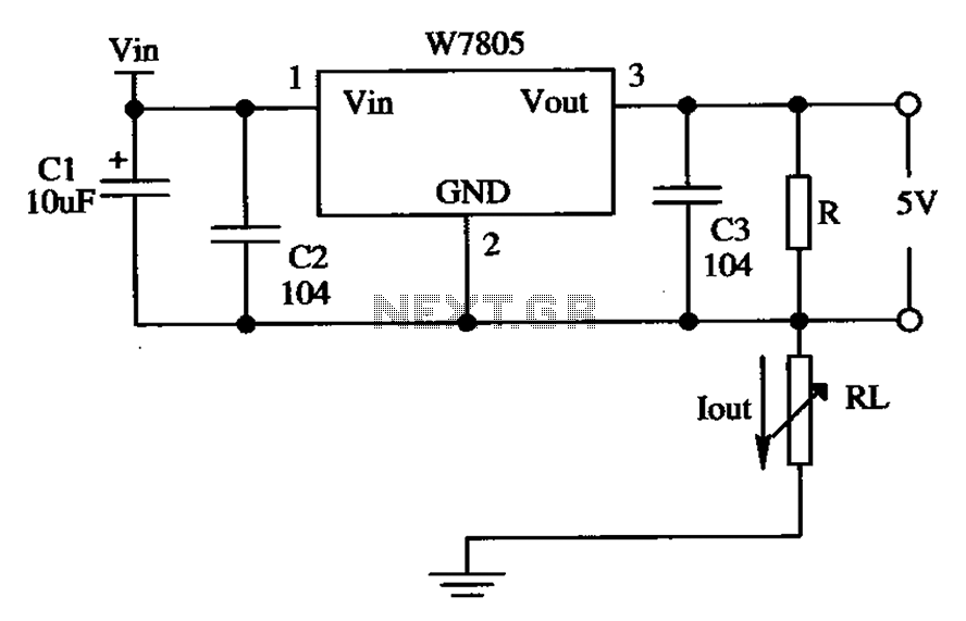
The circuit is composed of a W7805 positive current source application integration circuit that includes a voltage regulator. The W7805 regulator operates in suspension. A resistor is placed between its output terminal and the common terminal, forming a constant...