
Speed-Control Switch Circuit Circuit
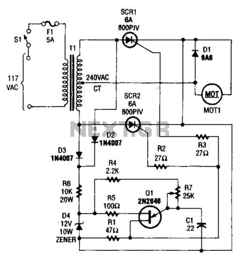
The circuit employs a center-tapped transformer rated for 240 volts, which serves as the primary power source. This transformer splits the AC voltage into two equal halves, providing the necessary input for the two silicon-controlled rectifiers (SCRs). The SCRs are positioned in a configuration that allows them to rectify the AC voltage into pulsating DC, which is then supplied to the load, identified as MOT1.
The UJT (Unijunction Transistor) ramp generator, designated as Q1, is integral to the operation of the SCRs. It generates trigger pulses that are essential for the SCRs to turn on and off at specific intervals. The ramp generator operates by charging a capacitor through a resistor until a predetermined voltage level is reached, at which point a pulse is emitted. This pulse is fed into the gate terminals of SCR1 and SCR2, enabling them to conduct and control the flow of current to MOT1.
The design ensures that the SCRs are triggered in such a manner that they effectively manage the power delivered to the load, allowing for precise control over the output characteristics. The use of a center-tapped transformer in conjunction with the UJT ramp generator provides a robust solution for converting AC power into a usable form of pulsating DC, suitable for various applications. The overall circuit design emphasizes reliability and efficiency in power management. A center-tapped 240-V transformer is used with two SCR devices to provide rectified ac (pulsating dc) to MOT1. Ql is a UJT ramp generator used to generate trigger pulses for SCR1 and SCR2. 🔗 External reference
Related Circuits
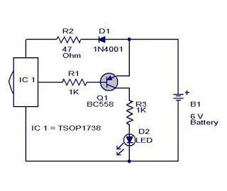
The cause may be dry solder joints, defective LEDs, or a flat battery (possibly due to a stuck key). The human eye cannot perceive infrared light, while a standard phototransistor such as the BP103 operates effectively in the infrared...

Voltage variations and power cuts adversely affect various equipment such as TVs, VCRs, music systems, and refrigerators. This simple circuit will protect costly equipment from high and low voltages and voltage surges when power resumes. It also produces a...
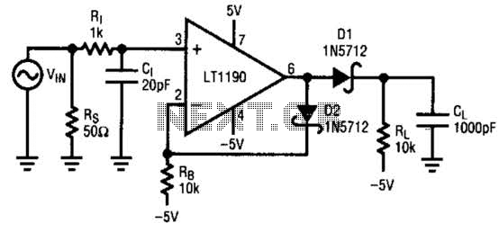
A fast pulse detector can be constructed using this circuit. A very fast input pulse will surpass the amplifier's slew rate, resulting in a prolonged overload recovery time. Implementing some degree of dv/dt limiting on the input can alleviate...
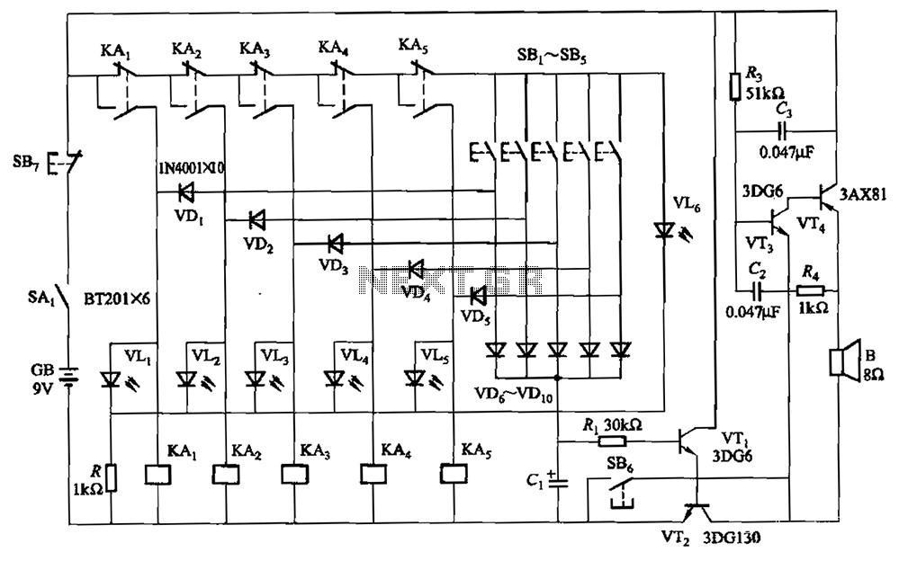
A relay-style circuit designed for a five electronic responder group. This circuit features self-locking capabilities, sound and light displays, time monitoring, and additional functions. The circuit includes a monitoring time button operated by the moderator. When this button is...
Adjustable 1.5 - 35 V DC Regulated Power Supply Circuit Diagram. This diagram includes three circuit designs and is categorized under Power Supply. For more information, refer to the detailed post titled "Adjustable 1.5 - 35 V DC Regulated...
This project involves a straightforward and practical 12V power supply circuit utilizing the LM7812 integrated circuit (IC). The LM7812 is a three-terminal fixed voltage regulator IC housed in a TO-220 package. It incorporates several built-in features such as thermal...