
25 Watt Audio Amplifier Circuit

The 25 Watt basic power amplifier circuit is structured to provide efficient amplification of audio signals while maintaining simplicity in design. The core of the amplifier typically consists of a differential input stage, a voltage gain stage, and a push-pull output stage, which work together to achieve high fidelity sound reproduction.
The input stage often employs bipolar junction transistors (BJTs) or field-effect transistors (FETs) configured in a differential arrangement to amplify the audio signal while rejecting common-mode noise. This stage is crucial for maintaining the integrity of the audio signal, ensuring minimal distortion as it passes through the amplifier.
Following the input stage, a voltage gain stage amplifies the signal further before it reaches the output stage. This stage may utilize a complementary push-pull configuration, which helps in driving the output transistors efficiently. The output stage is typically designed with transistors that can handle the required power levels, ensuring that the amplifier can deliver 25 Watts of output power to the connected load, usually a speaker.
In addition to the main components, the circuit may include various passive elements such as resistors and capacitors that help to stabilize the amplifier, control biasing, and filter out unwanted frequencies. Feedback loops are often incorporated to enhance linearity and reduce distortion, contributing to the overall performance of the amplifier.
Power supply considerations are also critical in the design of this amplifier. A regulated power supply is preferred to ensure consistent voltage levels, which is essential for maintaining audio quality. The design may accommodate both AC and DC power supplies, with appropriate rectification and filtering stages to provide the necessary DC voltage for the amplifier operation.
Overall, this 25 Watt power amplifier design achieves a balance between performance and cost-effectiveness, making it an appealing choice for audio enthusiasts and hobbyists looking to build their own amplification systems. Its simplicity and improved performance over standard STK modules make it a suitable candidate for various audio applications.This is a 25 Watt basic power amp that was designed to be (relatively) easy to build at a reasonable cost. It has better performance than the standard STK module amps that are used in practically every mass market stereo receiver manufactured today..
🔗 External reference
Related Circuits
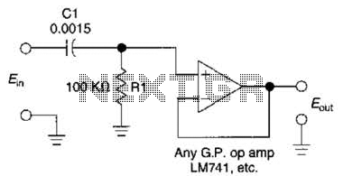
This simple 1 kHz filter utilizes a voltage follower and an RC section as its filtering element. For other frequencies, the -3 dB point is given by the formula 1/(6.28 Rl Cv), and the response decreases at a rate...

This voltmeter utilizes a pair of JFETs in a balanced-bridge source-follower amplifier circuit. Q1 and Q2 should be matched within 10% for IDSS. This configuration minimizes meter drift and maintains bridge balance over temperature. The described voltmeter is an advanced...
A 12V to 20000V inverter circuit diagram (stun gun) is presented. This circuit generates a very high voltage and must be used with caution to prevent electric shock. The transformer can produce over 1000V and amplify the voltage by...
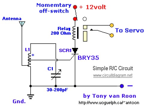
The diagram illustrates a straightforward and efficient receiver designed for activating garage doors, starter motors, alarms, warning systems, and various other applications. The silicon-controlled rectifier (SCR) utilized in this circuit features an exceptionally low trigger current of 30 µA,...
The problem with class-B amplifier design is that we start with an output stage in two halves, each with a non-linear response, which we then add together to try to give a linear response, i.e. so that a graph...
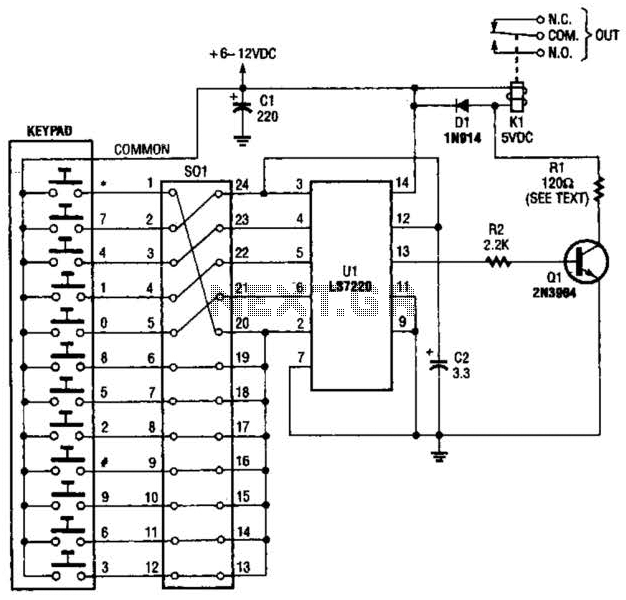
A block pinout diagram of the LS7220 keyless-lock IC is presented. The keypad must provide each key with a contact to a common connection. In this instance, the common connection is linked to the positive supply rail, allowing a...