
250 Watt PC power Supply
Control circuit
After switching the 230 Vac mains voltage on, an auxiliary voltage from the small 50 Hz transformer Tr1 powers the PWM controller SG3525. The error amplifier in the SG3525 compares a portion of the 13.8 output voltage (actual value) with the internal +5.1 V reference voltage (set value) and forms from it an error voltage for the pulse width modulator. The modulator sends alternate control pulses via its two outputs to the transformer Tr4. The pulse duration is inversely proportional to the error voltage. Increased loading on the +13.8 V output makes for wider pulses; lighter loading causes narrower pulses. The switching frequency of the power switches is 50 kHz. For higher frequencies the FETs are usable, but not the magnetic components salvaged from the PC power supply. The oscillator frequency is determined by the components attached to pin 5 and 6. R14 determines the dead time, which is absolutely necessary to avoid simultaneous conduction of the two switching transistors. Since they lacking the storage time limitation of bipolar transistors, a very small value can be set for the new FETs switches. With 1 us deadtime and 20 us period duration--50KHz--the FETs can theoretically conduct 95 % of the time and thus deliver energy to the output. Soft-start capacitor C13 charges after power-on, producing a soft-start with narrow pulses initially, then wider control pulses afterwards. Terminal (a) of the driver transformer Tr4 remains free. Just one half (26 t) of the primary turns (b - c) and the 16 turns of the secondary winding are sufficient to provide the necessary ratio of 0.6. With the magnetic components (output transformer, driver transformer, chokes...) stripped from a PC power supply, the new power supply delivers a max. power output of 250 W with efficiency up to 90 %. The power supply can handle 20 % overload for a short duration.
The described power supply circuit incorporates several advanced features to optimize performance and efficiency. The use of field-effect transistors (FETs) instead of bipolar transistors significantly enhances the switching speed and reduces conduction losses. The synchronous rectification method improves efficiency further by minimizing voltage drop across the rectifiers. The PWM controller (SG3525) is pivotal in regulating the output voltage, ensuring that the power supply can adapt to varying load conditions effectively.
The design also includes a robust inrush current limiting mechanism via the NTC resistor, which is crucial for protecting the circuit components during startup. The capacitors are strategically chosen to accommodate the ripple voltage requirements, ensuring stable output under varying load conditions.
The transformer design is critical, as it must be capable of operating efficiently at the increased frequency of 50 kHz. The re-winding of the driver transformer is necessary to ensure that the gate voltages supplied are adequate for the FETs to operate optimally. The soft-start feature incorporated into the circuit prevents sudden surges in current, thereby enhancing the longevity and reliability of the power supply.
Overall, this power supply design demonstrates a comprehensive understanding of electronic principles and the implementation of efficient components to achieve a high-performance output suitable for modern electronic applications.Up to 10 A continuous output current, or operation with 50 % ESD and 18 A peak current are possible without a fan if sufficient natural air flow is present and the ambient temperature does not exceed 30 °C. A small CPU fan (40 x 40 mm) should be used for more than 10 A continuous current. The heatsink surface is not large enough to keep the FETs junction temperature below the limit value ( Tj < 100 °C).
With a CPU fan the heat sink temperature remains below 28 °C (Tu = 20 °C). The following table shows the measured and calculated power dissipation Pv of the basic components at 250 W output power. The differences to the modified PC power supply consist of the following items: 1) two power FETs are used instead of bipolar transistors as power switches, 2) a synchronous rectifier on the secondary side instead of power diodes, 3) the elimination of a switch driver stage (current-proportional control), and 4) a simpler over-current and over-voltage monitor.
The magnetic components of AT-style PC power supplies don't vary much. They are usually designed for a switching frequency of 25... 40 kHz and a power output of 200... 240 W. The transformers on the S.M.P.S circuit boards are to be found often in either a small, or a somewhat larger size. I am not able to say, whether the larger size brings more power or if it is only an older design. [Note: the larger size is usually found in flyback supplies. ja] For the new power supply I preferred the larger transformers because they have more space available for additional turns in all three transformers.
The smaller transformers are completely filled with copper and insulation, and are therefore only marginally suitable for modification. This circuit section is uncomplicated. The common-mode choke Dr1 (mains filter) is followed by a NTC resistor for limiting the inrush current.
Its resistance amounts to 5 ohms cold, and after few minutes the warm resistance is less than one ohm. The 230 Vac rectifier is generously specified at 4 A, so no cooling is necessary. The values of capacitors of C3 and C4 is determined by the allowable ripple voltage Ubr, and the number of mains-voltage half-cycles to be bridged [i.e., 'hold-up' time required].
For Ubr = 25 V and zero half-cycles, two 470 uF capacitors in series are sufficient. This specification applies to maximum load during low mains-voltage Umin = 230 Vac - 15%. FET power switches were used for their short rise and fall times and the easy, component-saving driver circuit. If one is content with switching times of 100 ns, a small driver transformer and two gate resistors suffice for driving the FETs.
Unfortunately, there's no way to avoid re-winding the transformer secondary, which is needed to supply the proper gate voltages. The single turn and 2 x 8 turns must be removed from transformer Tr4. Instead of this, wind 2 x 16 turns (bifilar). A winding ratio of 16 : 26 and a 20 V control signal from IC1 provides the FETs' gates with 10 V of drive, enough to achieve the FETs' specified Ron of 0,75 ohms and thus very small conduction losses.
Dynamic (switching) losses at 50 kHz are negligible with the before-mentioned switching times. The PWM IC drives enough current to switch the FETs on and off quickly. Increasing the switching frequency from the original 33 kHz (PC power supply) to 50 kHz (new power supply) allows the transformer to more energy. You can't, however, arbitrarily increase frequency with a given transformer; the transformer is only usable over a certain frequency range.
Experiments showed the transformer can cope with a factor of 1.5 without problems (overheating). Control circuit After switching the 230 Vac mains voltage on, an auxiliary voltage from the small 50 Hz transformer Tr1 powers the PWM controller SG3525. The error amplifier in the SG3525 compares a portion of the 13,8 output voltage (actual value) with the internal +5,1 V reference voltage (set value) and forms from it an error voltage for the pulse width modulator.
The modulator sends alternate control pulses via its two outputs to the transformer Tr4. The pulse duration is inversely proportional to the error voltage. Increased loading on the +13.8 V output makes for wider pulses; lighter loading causes narrower pulses. The switching frequency of the power switches is 50 kHz. For higher frequencies the FETs are usable, but not the magnetic components salvaged from the PC power supply.
The oscillator frequency is determined by the components attached to pin 5 and 6. R14 determines the dead time, which is absolutely necessary to avoid simultaneous conduction of the two switching transistors. Since they lacking the storage time limitation of bipolar transistors, a very small value can be set for the the new FETs switches.
With 1 us deadtime and 20 us period duration--50KHz--the FETs can theoretically conduct 95 % of the time and thus deliver energy to the output. Soft-start capacitor C13 charges after power-on, producing a soft-start with narrow pulses initially, then wider control pulses afterwards.
Terminal (a) of the driver transformer Tr4 remains free. Just one half (26 t) of the primary turns (b - c) and the 16 turns of the secondary winding are sufficient to provide the necessary ratio of 0,6. With the magnetic components (output transformer, driver transformer, chokes...) stripped from a PC power supply, the new power supply delivers a max.
power output of 250 W with efficiency up to 90 %. The power supply can handle 20 % overload for a short duration. 🔗 External reference
Related Circuits
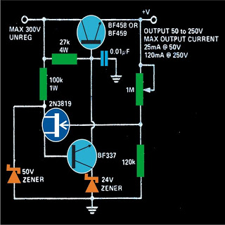
This power supply is designed to provide a regulated output voltage that is adjustable from zero to a maximum of 300 volts. All components should be mounted on heatsinks. While many power supply circuits are typically designed to deliver...
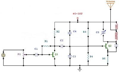
The circuit is a radio frequency (RF) oscillator that operates around 100 MHz. Audio signals captured and amplified by the electret microphone are sent to an audio amplifier stage constructed around the first transistor. The output from the collector...
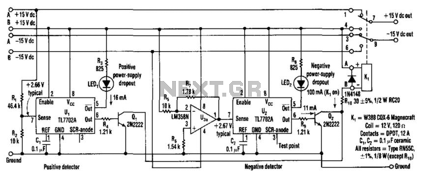
A supply monitor utilizing two TL7702A chips monitors the ±15-V supplies and activates the backup supply in the event of a voltage drop. While these chips are primarily designed for use as reset controllers in microprocessor systems, they are...
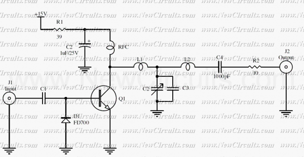
The RF circuit is a C-Class power amplifier. It is used in the last stage of transmitters. Its maximum power output is about 1 Watt. The circuit can be used in 3 frequency ranges: 30-100-200 MHz. More: The P-Out...
Features: 3-12 V, 1 A, over-current protection. This is a simple yet reliable device based on one of the oldest integrated voltage regulators, the LM723. R2 sets the output voltage. The maximum current is determined by the value of...
This is an image Schematic. No Description available. The provided input indicates the existence of a schematic image without further descriptive content. In the context of electronic schematics, such images typically represent the arrangement and interconnection of various electronic...