
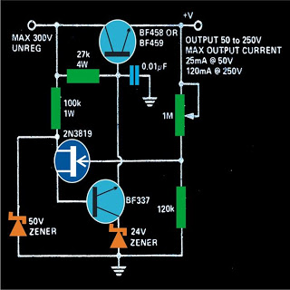
variable 0 to 300 volts regulated power
The power supply circuit operates by converting the alternating current (AC) from the mains into a direct current (DC) output through a bridge rectifier configuration. The bridge rectifier consists of four diodes arranged in a specific manner to allow current to flow in one direction, effectively converting AC to DC. The output of the bridge rectifier is then smoothed using a 10µF capacitor rated at 400 volts, which reduces voltage ripple and stabilizes the output voltage.
For the voltage adjustment feature, a variable resistor or potentiometer may be integrated into the circuit. This component allows the user to set the desired output voltage by varying the resistance, thereby controlling the voltage drop across the load. The circuit may also include an operational amplifier configured as a voltage follower to ensure a stable output voltage regardless of load variations.
Due to the high voltage capabilities of this power supply, all components must be rated appropriately to handle the maximum voltage and current. Heatsinks are essential for components that dissipate significant power, such as voltage regulators or transistors, to prevent overheating and ensure reliable operation.
Safety precautions are critical when working with high voltages. It is advisable to include fuses or circuit breakers to protect against overcurrent conditions, as well as proper insulation and enclosures to prevent accidental contact with live parts. Additionally, incorporating a voltmeter and ammeter can provide real-time monitoring of the output voltage and current, enhancing the usability of the power supply.
This design offers versatility for various applications, such as testing electronic components, powering high-voltage devices, or conducting experiments requiring a wide range of voltage outputs. Proper assembly and adherence to safety standards will yield a robust and reliable high-voltage power supply.This power supply can be used to obtain a regulated power output, variable right from zero to 300 volts maximum. All the devices should be mounted on heatsinks. You must havecome across many power supply circuits which are designed for supplying anywhere between 0 to 25 or at the most 40 volts DC, but the circuit presented here will give you
a robust power right from 0 to 300volts continuously variable. The input to the circuit may be derived directly from the mains AC after proper rectification and filtration using a bridge network and a 10u/400V capacitor. 🔗 External reference
Related Circuits
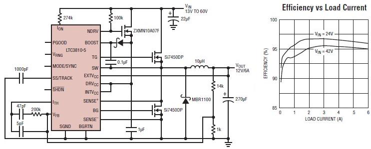
The LTC3810-5 synchronous step-down switching regulator controller allows for the design of a straightforward 12-volt switching power supply electronic project with minimal external components. This controller can directly reduce voltages from up to 60V, making it suitable for telecommunications...
The TDA2549 is a complete intermediate frequency (IF) circuit that includes automatic frequency control (AFC), automatic gain control (AGC), demodulation, and video preamplification capabilities for multistandard television receivers. It can process both positively and negatively modulated video signals in...
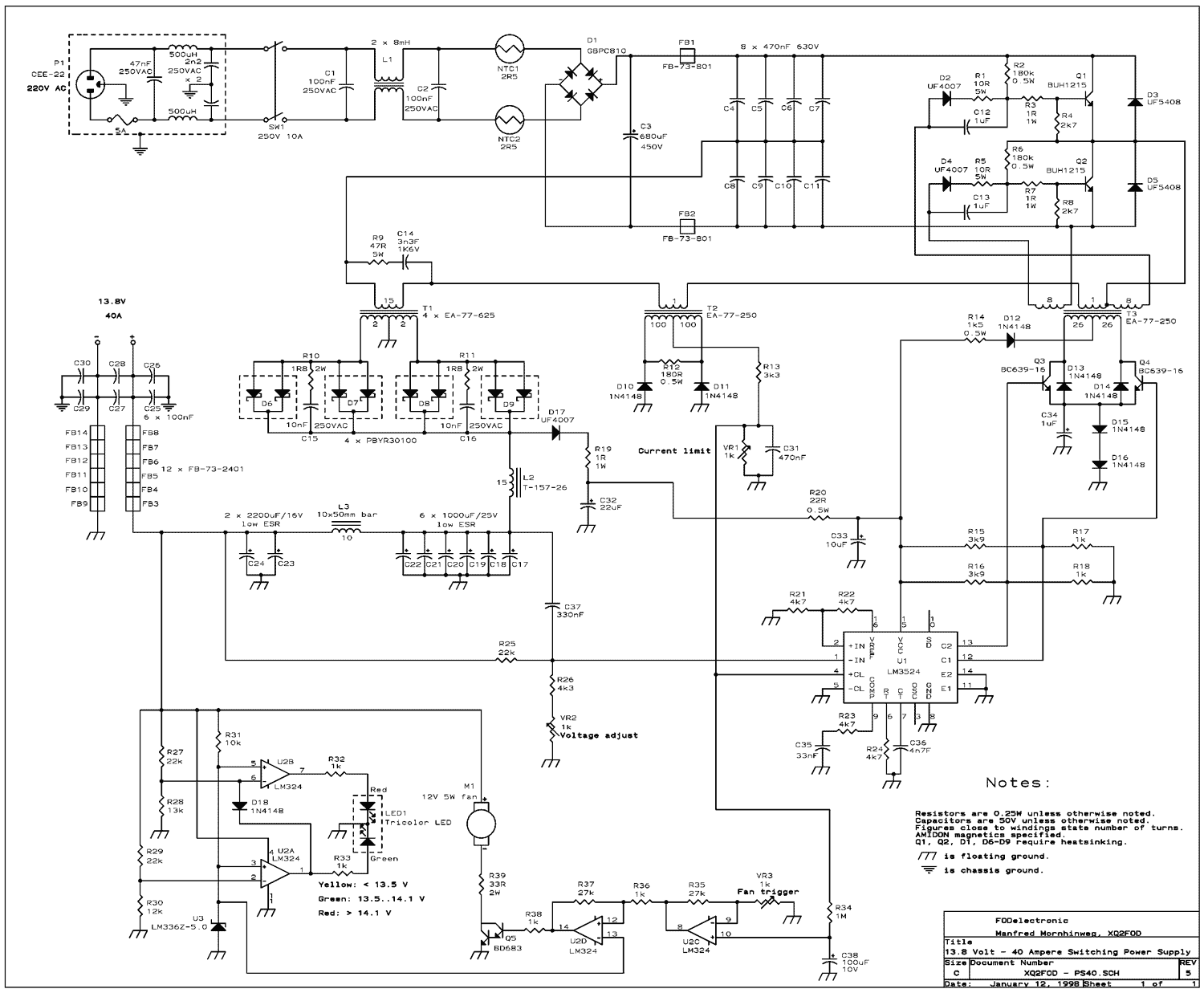
The present trend is to use ever higher frequencies. But by doing so it becomes more difficult to filter out the RF noise inevitably generated by the switching. So I decided to stay at a low switching frequency of...

This circuit is just an implementation of the 7805 integrated voltage regulator. What this little component does is to lower a voltage and stabilize it by reducing noise and ripple, in order for circuits to have the constant voltage...
In the circuit shown below, if the voltage at the output terminals rises above 6.2V, zener conducts charging capacitor C4. This voltage will fire the silicon-controlled rectifier (SCR), which quickly shorts across the supply rails blowing the fuse. The...
A NE555 integrated circuit (IC) is utilized for the design of a variable low-frequency oscillator, and a schematic is provided. The NE555 timer IC is a versatile and widely used device in various electronic applications, particularly in generating precise timing...