
27mhz transmitter circuit

The 27MHz transmitter circuit is a straightforward yet effective design primarily utilized in low-power applications such as remote controls, hobbyist projects, and basic wireless communication systems. The crystal oscillator configuration is crucial for generating a stable carrier frequency, which is essential for reliable transmission and reception.
The tuned circuit, consisting of the transformer and the capacitor, plays a vital role in determining the oscillator frequency. The ferrite slug allows for precise adjustments, enabling the designer to compensate for any variations in the crystal's frequency due to environmental factors. This flexibility is particularly important in practical applications where temperature fluctuations may occur.
The common emitter amplifier configuration of the transistor provides necessary gain while ensuring that the output signal remains within acceptable limits. The inclusion of the emitter resistor aids in biasing the transistor, promoting linear operation, which is essential for maintaining signal integrity.
The choice of a 10pF capacitor in conjunction with the transformer helps achieve the desired resonant frequency, while the 390Ω resistor safeguards the transistor from excessive current, which could lead to thermal runaway or damage. The transformer not only matches impedances but also enhances the overall efficiency of the transmitter by ensuring maximum power transfer to the antenna.
In summary, this 27MHz transmitter circuit exemplifies a fundamental approach to RF design, combining essential components to create a robust and reliable oscillator capable of stable frequency generation, suitable for various wireless applications.This is a design circuit for a simple 27MHz transmitter producing a carrier. The circuit can produces an unmodulated 27MHz signal and when picked up by a receiver. This is the figure of the circuit; The transmitter is a very simple crystal oscillator. The heart of the circuit is the tuned circuit consisting of the primary of the transformer and a 10p capacitor. These two components oscillate when a voltage is applied to them. The frequency is adjusted by a ferrite slug in the centre of the coil until it is exactly the same as the crystal. The crystal will then maintain the frequency over a wide range of temperature and supply voltage fluctuations.
The transistor is configured as a common emitter amplifier. It has a resistor on the emitter for biasing purposes but the 82p across the 390R effectively takes the emitter to the negative rail as far as the signal is concerned. The 390R resistor prevents a high current passing through the transistor as the resistance of the transformer is very low.
The tuned circuit operates at exactly the third harmonic (also called the third overtone - an overtone is a multiple of a fundamental frequency) of the crystal so that the crystal will oscillate at its third overtone (27MHz) and in-turn, keep the frequency of the circuit stable. The transformer in the collector of the transistor performs two functions. 1. It matches the impedance of the transistor to the impedance of the antenna, and 2. Creates a resonant circuit at 27MHz to make sure the crystal oscillates at this frequency. 🔗 External reference
Related Circuits
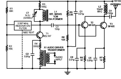
The circuit presented here is a powerful AM transmitter utilizing a ceramic resonator/filter operating at 3.587 MHz. This circuit primarily relies on a transistor for its core functionality. It is possible to use resonators/filters of other frequencies, such as...
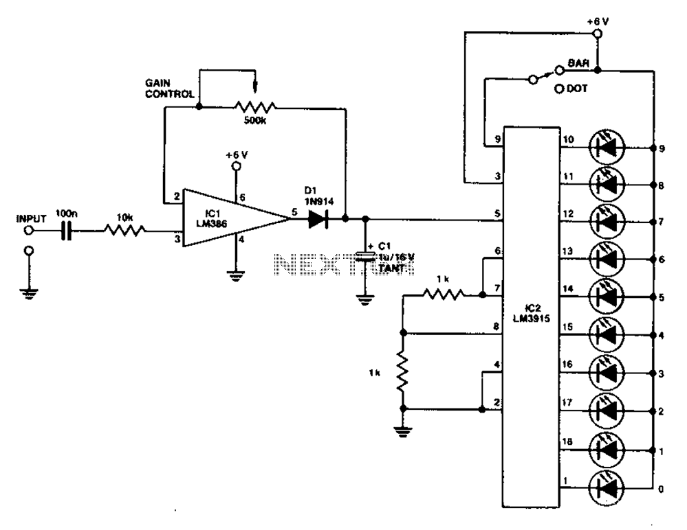
A simple level power meter designed to provide a high-fidelity sound system with a bar or dot matrix display. The green LED display indicates levels from 0 to 7; level 8 is shown in yellow, and level 9 is...
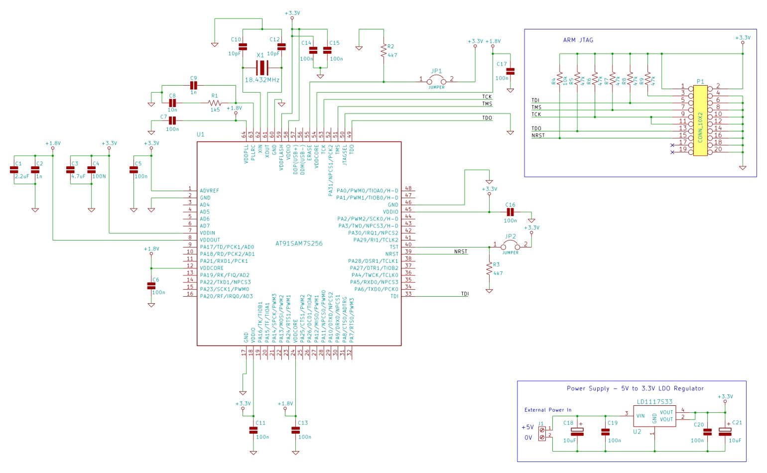
The minimum number of supporting components required to build a circuit using AT91SAM7S microcontrollers. This example uses the AT91SAM7S256 ARM7 microcontroller. To construct a circuit utilizing the AT91SAM7S256 ARM7 microcontroller, a minimal set of supporting components is essential to ensure...
The FM302E-I-type FM transmitter exciter is manufactured by NEC Corporation, Japan, and features a 1210 motherboard. It utilizes direct frequency modulation of the carrier signal, employing phase-locked frequency stabilization and frequency synthesis techniques. The front power amplifier is based...
This compact transmitter employs a Hartley-type oscillator. Typically, the capacitor in the tank circuit would connect to the base of the transistor; however, at VHF frequencies, the base-emitter capacitance of the transistor behaves like a short circuit, effectively maintaining...
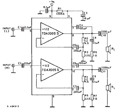
The TDA2005 car audio amplifier circuit is specifically designed for use in devices such as car radios, CD players, and similar equipment. This amplifier is based on the TDA2005 audio integrated circuit (IC), capable of delivering a maximum output...
Warning: include(partials/cookie-banner.php): Failed to open stream: Permission denied in /var/www/html/nextgr/view-circuit.php on line 713
Warning: include(): Failed opening 'partials/cookie-banner.php' for inclusion (include_path='.:/usr/share/php') in /var/www/html/nextgr/view-circuit.php on line 713