
tda2005 car audio amplifier circuit diagram project
The TDA2005 car audio amplifier circuit is a versatile solution for automotive audio applications, providing high-quality sound amplification with efficient power management. The device's bridge mode configuration is particularly advantageous for applications requiring higher power output while maintaining low distortion levels. The integration of short circuit and thermal protection mechanisms enhances reliability, making the amplifier suitable for various automotive environments where conditions may vary significantly.
In terms of circuit design, the TDA2005 can be easily integrated into existing audio systems due to its low component count and straightforward implementation. The Multiwatt 11 package allows for efficient thermal dissipation, crucial for maintaining performance during prolonged use. The amplifier's capability to operate within a wide voltage range ensures compatibility with various power supply configurations found in automotive applications.
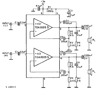
Overall, the TDA2005 amplifier is an excellent choice for enhancing audio performance in vehicles, offering flexibility in configuration and robust protection features, making it suitable for both novice and experienced designers in the field of automotive electronics.This TDA2005 car audio amplifier circuit is specially designed to work on devices like : car radios, cd-players and similar devices. This car radio audio amplifier circuit is based on the TDA2005 audio IC which can provide a maximum output power of 20 watts into a 4 ohms load, connected in bridge mode configuration.
The TDA2005 audio IC is a c lass B audio amplifier designed in a Multiwatt 11 package and can be ordered in two types TDA2005M used for bridge mode application or TDA2005S used in stereo applications. If the TDA2005 is used in stereo mode it can deliver a 10 + 10 watts output power in a 2 ohms load. The advantage of using the TDA2005 audio amplifier in bridge mode configuration is that the total harmonic distortion ( THD) is 1% and the THD for the stereo configuration mode is 10 %.
This audio amplifier IC supports a wide range of input voltage from 8 volts up to 18 volts and it has many features like : short circuit protection, overrating chip temperature, low external components required, bridge or stereo booster amplifiers with or without boostrapand with programmable gain and bandwidth, no electrical isolation between the package and the heatsink. 🔗 External reference
Related Circuits
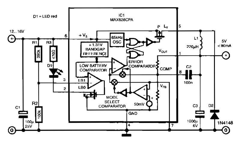
The circuit utilizes the MAX638CPA 5V CMOS Step Down Adjustable Switching Regulator IC, which converts an input voltage of 12 to 16 VDC into a stable 5VDC output. It requires only nine additional external components to complete the circuit....
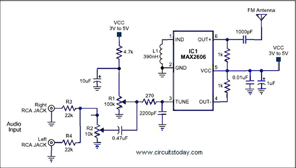
A simple single-chip FM transmitter circuit with a diagram and schematic using the IC MAX 2606, which is a high-performance voltage-controlled oscillator (VCO). The FM transmitter circuit utilizing the MAX 2606 is designed for efficient frequency modulation of audio signals....
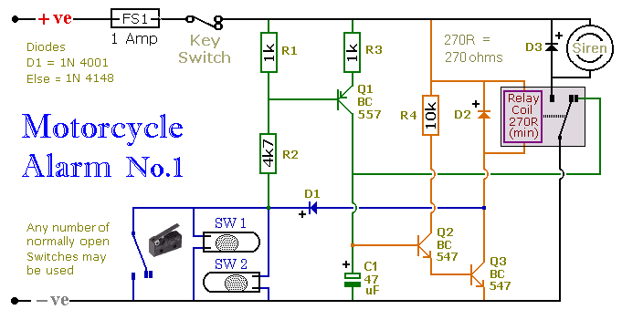
This circuit includes a timed output and an automatic reset feature. It can be manually operated using a key switch or a concealed switch. By incorporating an external relay, the circuit will automatically engage or immobilize the machine each...
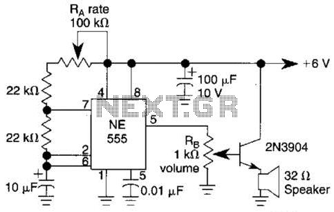
Ra sets the rate while RH sets the volume of clocks in the speaker. The 555 is configured as a low frequency oscillator. The circuit is powered by a 6 V battery. The circuit utilizes a 555 timer IC configured...
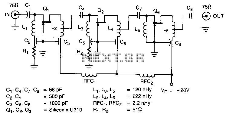
The amplifier circuit is designed for a 225 MHz center frequency, with a 1 dB bandwidth of 50 MHz, low input VSWR in a 75-ohm system, and a gain of 24 dB. Three stages of U310 FETs are utilized...
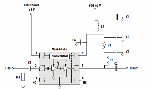
This application note discusses the use of Avago Technologies' MGA-675T6 for 5-6 GHz applications. The MGA-675T6 is internally integrated with shutdown and biasing circuitry, which simplifies the external circuitry. The shutdown feature allows the low noise amplifier (LNA) to...